Eureka AIR delivers breakthrough ideas for toughest innovation challenges, trusted by R&D personnel around the world.

Electric leakage point positioning method for aiming at floating gate

A positioning method and leakage point technology, applied in the direction of measuring electricity, measuring electrical variables, testing dielectric strength, etc., can solve the problem of low positioning accuracy and achieve the effect of ensuring effectiveness

Active Publication Date: 2018-10-02
WUHAN XINXIN SEMICON MFG CO LTD
View PDF6 Cites 2 Cited by
  • Summary
  • Abstract
  • Description
  • Claims
  • Application Information

AI Technical Summary

Problems solved by technology

[0003] The traditional positioning method is to roughly locate the location of the leakage point by grabbing hot spots with a laser or a low-light microscope. The positioning accuracy is in the area of ​​5um×3um or 3um×5um, and the positioning accuracy is very low.

Method used


Image

  • Electric leakage point positioning method for aiming at floating gate
  • Electric leakage point positioning method for aiming at floating gate
  • Electric leakage point positioning method for aiming at floating gate

Examples


Embodiment Construction

[0026] The present invention will be further described below in conjunction with the accompanying drawings and embodiments.

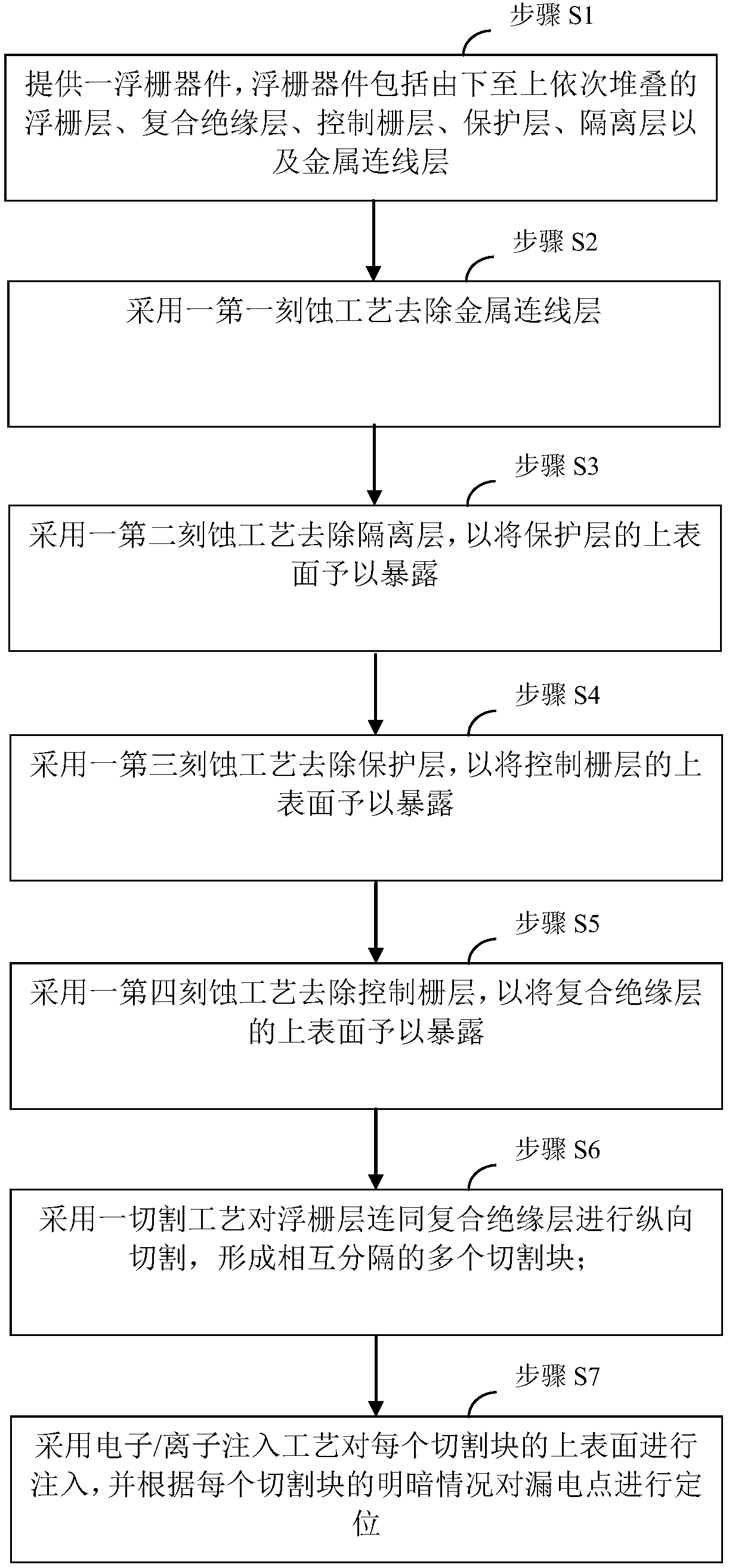
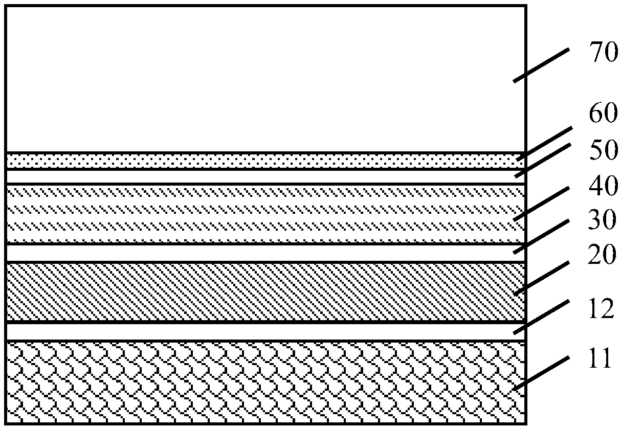
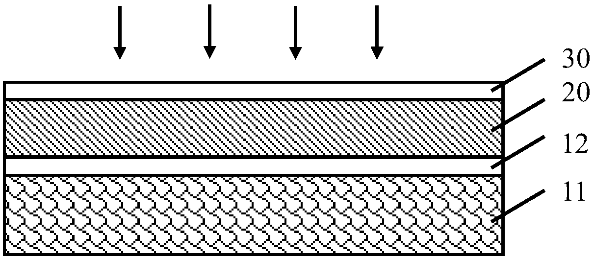
[0027] In a preferred embodiment, as figure 1 As shown, a method for positioning the leakage point of the floating gate is proposed, and the schematic diagram of the formed structure can be shown as Figure 2 ~ Figure 4 As shown, wherein, the leakage point positioning method for the floating gate may include:

[0028] Step S1, providing a floating gate device, which includes a floating gate layer 20, a composite insulating layer 30, a control gate layer 40, a protective layer 50, an isolation layer 60, and a metal wiring layer 70 stacked sequentially from bottom to top;

[0029] Step S2, using a first etching process to remove the metal wiring layer 70;

[0030] Step S3, using a second etching process to remove the isolation layer 60, so as to expose the upper surface of the protection layer 50;

[0031] Step S4, using a third etching process to remo...


PUM


Abstract

The invention relates to the field of semiconductor technology, and particularly to an electric leakage point positioning method for aiming at a floating gate. The method comprises the steps of S1, supplying a floating gate device; S2, eliminating a metal connecting line layer by means of a first etching process; S3, eliminating an insulating layer by means of a second etching process; S4, eliminating a protecting layer by means of a third etching process; S5, eliminating a control gate layer by means of a fourth etching process; S6, performing longitudinal cutting on the floating gate layer and a composite insulating layer by means of a cutting process, thereby forming a plurality of cutting blocks which are separated from one another; and S7, performing implantation on the upper surfaceof each cutting block by means of an electron / ion implantation process, and positioning the electric leakage point according to the brightness condition of each cutting block; wherein the fourth etching process is a wet etching process in which choline hydroxide solution is utilized. The electric leakage point positioning method has advantages of realizing accurate positioning in the composite insulating layer, further accurately positioning the electric leakage point in the floating gate, and ensuring effectiveness in testing breakdown voltage.

Description

technical field [0001] The invention relates to the technical field of semiconductors, in particular to a leakage point positioning method for floating gates. Background technique [0002] For floating gate products, the quality of oxide breakdown resistance is a key parameter for process control. The breakdown voltage test is an important method to evaluate the breakdown resistance quality of oxides. The location of the failure point or leakage point in the analysis of the breakdown voltage test failure sample is an essential step in failure analysis. [0003] The traditional positioning method is to roughly locate the location of the leakage point by grabbing the hot spot with a laser or a low-light microscope. The positioning accuracy is in the area of ​​5um×3um or 3um×5um, and the positioning accuracy is very low. Contents of the invention [0004] In view of the above problems, the present invention proposes a method for locating the leakage point of the floating ga...

Claims


Application Information

Patent Timeline
Patent Type & Authority Applications(China)
IPC IPC(8): G01R31/12
CPCG01R31/129
Inventor 苏秋雷李桂花仝金雨蔚倩倩杜晓琼
Owner WUHAN XINXIN SEMICON MFG CO LTD
Why Eureka
Eureka Blog
Learn More