
Gas distribution device suitable for dividing wall column

A gas distribution device and technology for gas distribution, applied in the field of chemical rectification, can solve the problems of too many transmission parts, unbalanced adjustment, gas-liquid phase separation, etc., and achieve the effect of less transmission parts, simple structure and flexible deployment.

Inactive Publication Date: 2018-10-09
王静
View PDF7 Cites 4 Cited by
  • Summary
  • Abstract
  • Description
  • Claims
  • Application Information

AI Technical Summary

Problems solved by technology

[0007] The invention provides a gas distribution device suitable for the next-door tower, which adopts an integral structure to flexibly adjust the gas flow on both sides of the partition, has a simple structure and is easy to control, and solves the need for separate control of two gas distribution devices in the prior art , there are many transmission parts, the gas-liquid phase is separated and cannot be adjusted in a balanced manner

Method used


Image

  • Gas distribution device suitable for dividing wall column
  • Gas distribution device suitable for dividing wall column
  • Gas distribution device suitable for dividing wall column

Examples


Embodiment 1

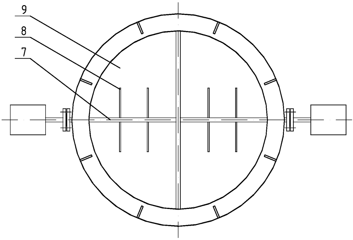
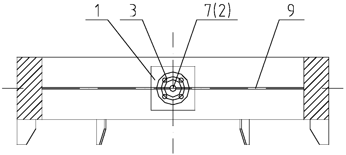
[0050] Embodiment 1: In this embodiment, the diameter of the next-door tower is 800 mm, the outer diameter of the gas distribution device housing 4 is 796 mm, the inner diameter is 736 mm, and the height is 100 mm. The thickness of the baffle plate 5 at the center of the housing 4 is 20 mm. The surface and the lower surface are respectively flush with the upper and lower surfaces of the shell, and the upper surface coincides with the lower surface of the dividing plate of the next-door tower, so as to ensure that the materials on both sides of the baffle plate 5 are isolated from each other. There are circular through holes with a diameter of 15 mm on both sides of the horizontal direction of the housing 4 and the tower body, and a rotating shaft 7 is arranged in the middle of the circular through hole. The diameter of the rotating shaft 7 is 15 mm, and the outer side of the rotating shaft 7 extends out of the tower. body, and is connected with a shaft coupling 3, and the outer...

Embodiment 2

[0052] Embodiment 2: In this example, the diameter of the next-door tower is 2000mm, the outer diameter of the gas distribution device housing 4 is 1996mm, the inner diameter is 1896mm, and the height is 200mm. The thickness of the baffle plate 5 in the center of the housing 4 is 30mm. The side and the tower body are respectively provided with a circular through hole with a diameter of 20 mm, the diameter of the rotating shaft 2 7-2 passing through the circular through hole is 20 mm, the depth of the groove on the baffle plate 5 is 5 mm, and the rotating shaft 2 7-2 is inserted into the in the groove and can rotate freely. The device adopts a three-blade structure, and in addition to the rotating shaft 2 7-2, it also includes a rotating shaft 1 7-1 and a rotating shaft 3 7-3, both of which have a diameter of 20 mm. One end of -3 is inserted into the groove in the casing 4, and the other end is inserted into the groove in the baffle plate 5, and can rotate freely. Blade 1 9-1,...


PUM


Abstract

A gas distribution device suitable for a dividing wall column is characterized by comprising a motor, a motor shaft, a coupler, a shell, a retaining shell, a ribbed plate, a rotating shaft, fins, blades, a gas flowmeter, a DCS control system and a pipeline. Circulation area in the gas distribution device is controlled through rotation of the blades to change gas flow on two sides of a partition ofthe dividing wall column. The defects that two gas distribution devices are needed for respective control, there are many transmission parts, gas-liquid phases are separated and balanced adjusting cannot be realized in the prior art are overcome. The gas distribution device has the advantages of being flexible in distribution, few in transmission part, small in space occupied in the dividing wallcolumn and convenient for mounting.

Description

technical field [0001] The invention relates to a gas distribution device suitable for a partition tower, which belongs to the field of chemical distillation. Background technique [0002] The dividing wall tower is a new type of energy-saving rectification process. It refers to setting a vertical partition inside the rectification tower, which divides the rectification tower into a public rectification section above the partition, a public stripping section below the partition, and a partition. There are four parts: the pre-separation section on both sides and the sideline production section in the middle. For the separation of ternary mixture systems, at least two column operations are required to obtain the three different components. The dividing wall column can integrate the pre-separation column and the main column in one column body, which reduces the back-mixing of intermediate substances and improves thermodynamic efficiency. Compared with traditional distillation ...

Claims


Application Information

Patent Timeline
Patent Type & Authority Applications(China)
IPC IPC(8): B01D3/32B01D3/14B01D3/42
CPCB01D3/14B01D3/32B01D3/42
Inventor 王静高笑侯振凯王怀强侯震
Owner 王静
Learn More