Industrial waste water treatment device

A kind of treatment device, technology of industrial waste water

Inactive Publication Date: 2018-10-09
杨勇
View PDF0 Cites 1 Cited by
  • Summary
  • Abstract
  • Description
  • Claims
  • Application Information

AI Technical Summary

Problems solved by technology

[0003] The technical problem to be solved by the present invention is: In order to solve the problem that the existing industrial wastewater treatment device cannot effectively treat the water pollution and the biofilm activity is easily affected, the present invention provides an industrial wastewater treatment device that uses The first-level treatment mechanism set up by the shell, fastening frame, mesh screen, filter layer, mixing tank, activated carbon layer, main shaft, collecting bucket, circulation pipe and agitator has a stable structure and uses physical methods for preliminary treatment of industrial wastewater. The rotation can quickly neutralize the pH of the wastewater, reduce the pollution of the wastewater, and can fully absorb the activated carbon to effectively treat the wastewater; using the diversion seat, end cover, fixed rod, biofilm layer, electric control valve, and outlet pipe , heat exchange pipe, heat preservation tank, and top flow pipe set up a secondary treatment mechanism, which can carry out a hierarchical secondary treatment process according to the pollution degree of the wastewater, with high treatment efficiency, and the temperature control outside the biofilm is stable and not easy to inactivate , the present invention solves the shortcoming that the current biofilm process requires high ambient temperature

Method used


Image

  • Industrial waste water treatment device
  • Industrial waste water treatment device
  • Industrial waste water treatment device

Examples


Embodiment Construction

[0019] The present invention is described in further detail now in conjunction with accompanying drawing. These drawings are all simplified schematic diagrams, which only illustrate the basic structure of the present invention in a schematic manner, so they only show the configurations related to the present invention.

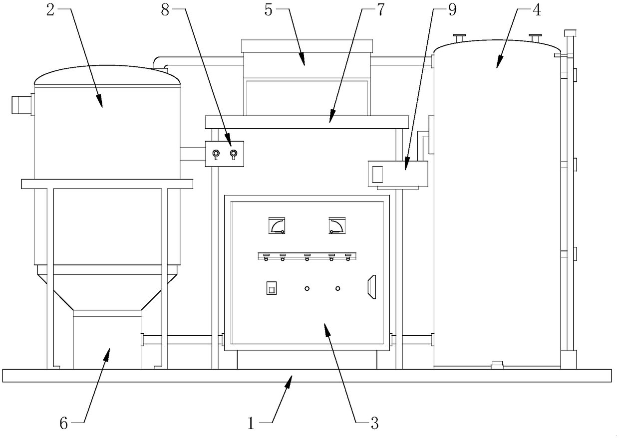
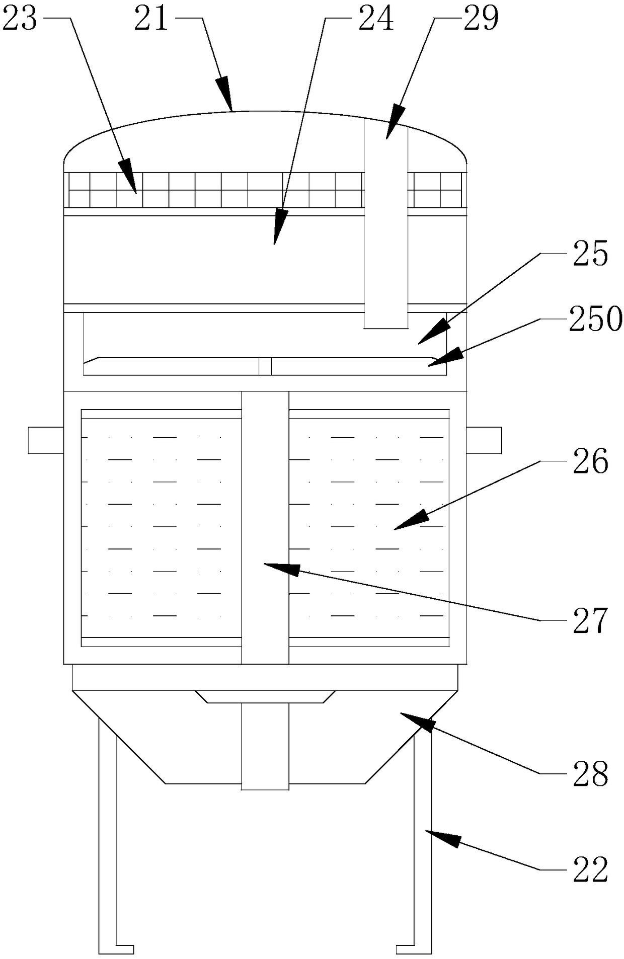
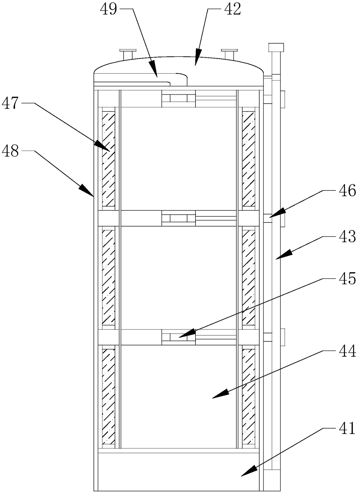
[0020] see Figure 1-3 , the present invention provides a technical solution: an industrial wastewater treatment device, including a primary treatment mechanism 2, a base 1 and a secondary treatment mechanism 4, the primary treatment mechanism 2 is fixed on the left side of the upper end of the base 1, and the primary treatment mechanism 2 The power box 6 is installed at the lower end, the secondary processing mechanism 4 is fixed on the right side of the upper end of the base 1, a fixed platform 7 is installed in the middle of the upper end of the base 1, and an electric control cabinet 3 is installed at the lower end of the fixed platform 7, and the electric...


PUM


Abstract

The invention discloses an industrial waste water treatment device. The industrial waste water treatment device comprises a first-stage treatment mechanism, a pedestal and a second-stage treatment mechanism; a power box is arranged at the lower end of the first-stage treatment mechanism; a fixed platform is arranged in the middle of the upper end of the pedestal; an electric control cabinet is arranged at the lower end of the fixed platform; a circulating valve is arranged at the upper end of the fixed platform; the industrial waste water is preliminarily treated by the first-stage treatment mechanism which is provided with a shell, a fastening frame, a net sieve, a filtering layer, a mixing groove, an activated carbon layer, a main shaft, a flow collecting bucket, a circulating pipe and astirrer as well as by using a physical method; and a hierarchical secondary treatment process is conducted by the second-stage treatment mechanism which is provided with a flow guide base, an end cover, a fixed rod, a biological film layer, an electric control valve, a flow outlet pipe, a heat exchange pipe, a heat-insulating tank and a top flow pipe and according to the pollution degree of the waste water, so that the treatment efficiency is high and the defect that the existing biological film process has high requirement on the environment temperature is overcome.

Description

technical field [0001] The invention relates to the technical field related to wastewater treatment, in particular to an industrial wastewater treatment device. Background technique [0002] Industrial wastewater treatment refers to the water used in the industrial production process is properly treated and reused for production or properly discharged from the factory, including the management of production water and the measures taken to facilitate the treatment of wastewater. The amount and quality of industrial wastewater varies with products and It depends on the production process and changes greatly, so it is not suitable to use typical data. The biofilm process of industrial wastewater is an artificial enhancement of the soil self-purification process. It mainly removes soluble and colloidal organic pollutants in the wastewater. At the same time, it also has a certain nitrification ability for ammonia nitrogen in the wastewater. The biofilm method is used in the treat...

Claims


Application Information

Patent Timeline
IPC IPC(8): C02F9/14
CPCC02F9/00C02F1/001C02F1/283C02F1/66C02F3/00
Inventor 杨勇
Owner 杨勇
Why Eureka
Try Eureka