
Glass kiln furnace production system

A glass kiln and production system technology, applied in glass production and other directions, can solve the problems of sand unloading, affecting production, easy agglomeration of sand, etc., to improve the dust collection effect and reduce pollution.

Active Publication Date: 2018-10-09
江苏慕宁建设工程有限公司
View PDF4 Cites 0 Cited by
  • Summary
  • Abstract
  • Description
  • Claims
  • Application Information

AI Technical Summary

Problems solved by technology

[0004] Most of the existing glass processing factories use the above-mentioned raw material homogenization warehouse to homogenize the sand, and then mix the homogenized sand with other raw materials and put them into the kiln head bin to melt into liquid, and then shape and The glass product is made through the cooling process, and the fuel is burned in the melting kiln, resulting in a high temperature above 1570 ℃, melting the glass raw material, and then going through the molding process, and then entering the annealing kiln. In some areas in northern China where the temperature is close to below zero, the above mentioned When installed in the raw material homogenization warehouse, the sand is easy to agglomerate, which will cause the sand to be unable to be discharged from the bottom of the warehouse normally and affect the normal production

Method used


Image

  • Glass kiln furnace production system
  • Glass kiln furnace production system
  • Glass kiln furnace production system

Examples


Embodiment 1

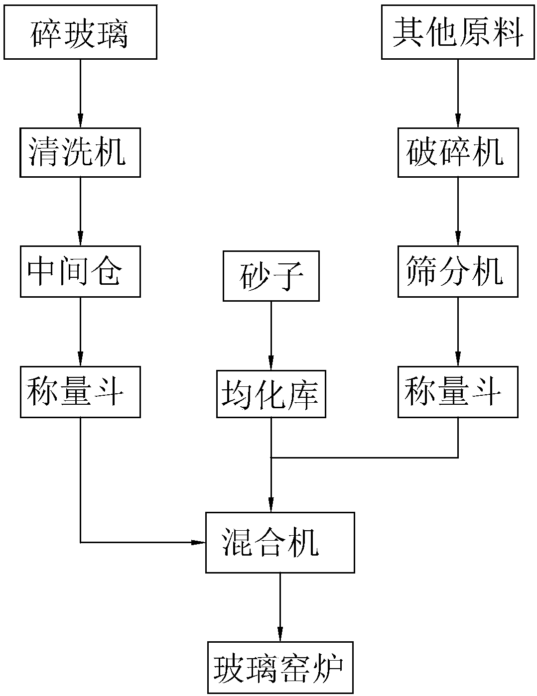
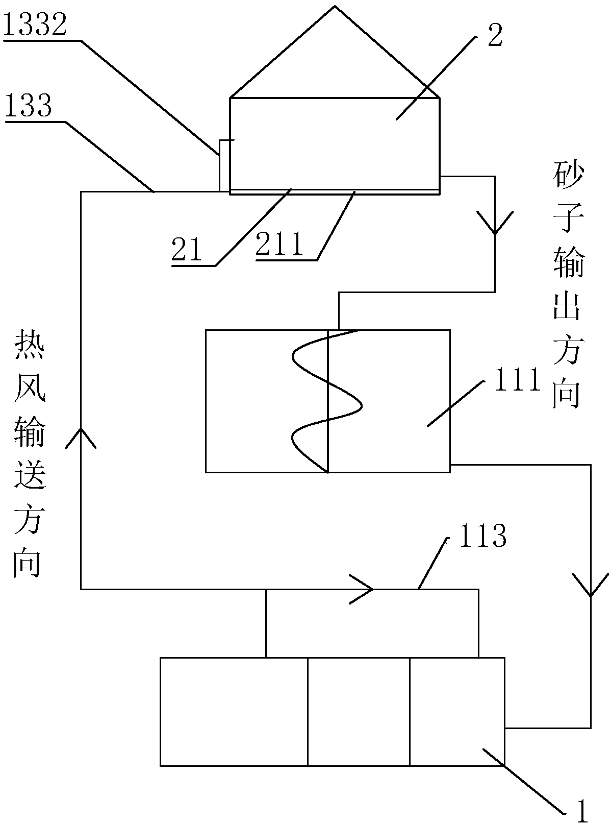
[0048] Embodiment 1: a kind of glass kiln production system, such as figure 2 and 3 As shown, a glass furnace 1 is included, and the glass furnace 1 includes a melting furnace 11, a tin tank 12 and an annealing furnace 13 integrally connected in sequence, and a mixer 111 for mixing raw materials is connected to the feeding port of the melting furnace 11, A homogenization storehouse 2 is connected to the feed port of the mixer 111 . Both sides of the melting furnace 11 are provided with a regenerator 112 , and the top of the regenerator 112 communicates with the melting furnace 11 to intermittently heat the melting furnace 11 .

[0049] Such as figure 2 and 5 As shown, a metal bearing plate 21 is arranged in the homogenization storehouse 2 , and a cavity 211 is provided inside the metal bearing plate 21 . Sand is piled directly on the metal bearing plate 21.

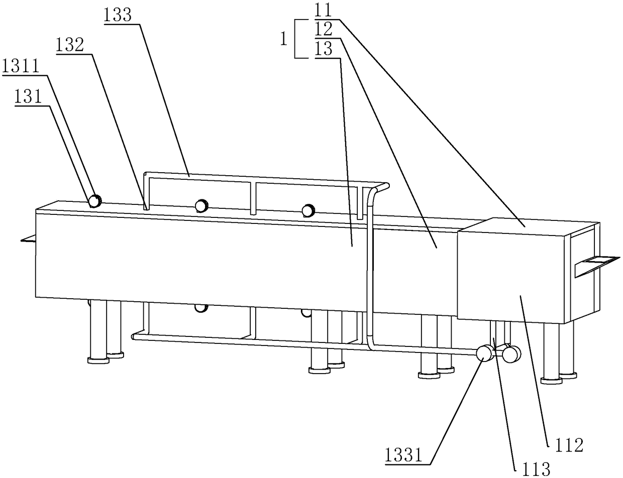
[0050] Such as image 3 , 4 Shown in and 6, an air inlet 131 and an air outlet 132 are arranged on the lehr 13...

Embodiment 2

[0056] Embodiment 2: a kind of glass kiln production system, the difference with embodiment 1 is, as Figure 12 and 13 As shown, in this embodiment, the driving mechanism is the exhaust fan 73 , the air inlet 131 of the exhaust fan 73 communicates with the end of the dust collection pipe 7 away from the hopper 45 , and the air outlet of the exhaust fan 73 communicates with the dust bag 71 . The exhaust fan 73 directly produces a suction force in the dust collection pipe 7 to transport to the dust collection bag 71. When the sand falling on the conveyor belt 6 generates dust, this part of the dust passes through the dust collection pipe under the action of the suction force. 7 is collected in the dust bag 71, thereby reducing the dust from raising into the air and causing pollution to other places.


PUM


Abstract

The invention discloses a glass kiln furnace production system, belongs to production equipment of glass and aims to provide a glass kiln furnace production system for preventing sand in a homogenization tank from being easily frozen. According to the technical scheme, the glass kiln furnace production system comprises a glass kiln furnace and a homogenization tank, wherein the homogenization tankis used for homogenizing sand; the glass kiln furnace comprises a melting furnace, a tin tank and an annealing kiln which are connected in sequence; a mixing machine is connected with a feeding holeof the melting furnace; the feeding hole of the mixing machine is connected with the output hole of the homogenization tank; an air inlet and an exhaust hole are formed in the annealing kiln; the airinlet is connected with an air blower; a metallic holding plate for holding sand is arranged on the bottom plate inside the homogenization tank; a cavity is formed inside the metallic holding plate; awaste heat recycling tube is arranged on the annealing kiln; an exhaust fan is arranged on the waste heat recycling tube; one end of the waste heat recycling tube is communicated with the exhaust hole; the other end of the waste heat recycling tube is communicated with the cavity.

Description

technical field [0001] The invention relates to a glass production equipment, in particular to a glass kiln production system. Background technique [0002] The purpose of silica sand homogenization is to stabilize the composition, particle size and moisture content of silica sand to ensure stable production of flat glass. Usually, the homogenization of silica sand needs to be carried out in the silica sand homogenization warehouse, and the silica sand outside the silica sand homogenization warehouse is transported into the corresponding position of the silica sand homogenization warehouse by a stacking device for stacking. [0003] The Chinese patent with the publication number CN204490741U discloses a high-efficiency and energy-saving raw meal homogenization storage device. The discharge port of the hoist is connected to the feed port of the conveying chute, and the discharge port of the conveying chute is connected to the distributor. The dispenser is connected with the ...

Claims


Application Information

Patent Timeline
IPC IPC(8): C03B25/08C03B1/00
CPCC03B1/00C03B25/08Y02P40/50
Inventor 宋加喜陈立新
Owner 江苏慕宁建设工程有限公司
Features
  • Generate Ideas
  • Intellectual Property
  • Life Sciences
  • Materials
  • Tech Scout
  • Unparalleled Data Quality
  • Higher Quality Content
  • 60% Fewer Hallucinations
Learn More