Application method of rigid drilling tool for coiled tubing sidetracking horizontal well

A technology of sidetracking horizontal wells and application methods, which is applied in the direction of drilling equipment and methods, directional drilling, drilling equipment, etc., and can solve problems such as elastic-plastic deformation, small actual footage, and small inner hole area of ​​coiled tubing, etc., to increase the length , extend the length, overcome the effect of short drilling section

Active Publication Date: 2020-03-17
BC P INC CHINA NAT PETROLEUM CORP +1
View PDF5 Cites 0 Cited by
  • Summary
  • Abstract
  • Description
  • Claims
  • Application Information

AI Technical Summary

Problems solved by technology

In order to solve this problem, a special downhole tool-hydraulic vibration damper is connected to the coiled tubing. However, the field tests of coiled tubing drilling in recent years have proved that with the increase of the length of the horizontal section of the sidetracked horizontal well, the coiled tubing With the deepening of the drilling section, the increase of the well deviation, and the hardening of the formation, the continuous drilling of the coiled tubing is becoming more and more difficult. Although the hydraulic vibrator is used, the actual footage increased is not much
Especially when the spiral bending of the coiled tubing is severe, the section of the coiled tubing at the point of contact with the well wall will suddenly appear elastic-plastic deformation, for example, when the coiled tubing of Φ60.325mm is drilled in a Φ118mm wellbore, the Under the action of WOB, the coiled tubing will undergo spatial helical bending. When the WOB continues to increase to 1.5 tons, the section of the coiled tubing in the contact point area with the well wall will suddenly undergo elastic-plastic deformation, and the area of ​​the inner hole will suddenly decrease. like figure 2 The A shown is the easily deformable section, image 3 where B is the free state area of ​​the easily deformable section, C is the limit state area of ​​the easily deformable section, by figure 2 and image 3 It can be seen that when the helical bending of the coiled tubing is serious, the easily deformable section A increases, and after it changes from the free state area B to the limit state area C, the inner hole area of ​​the coiled tubing becomes very small, resulting in continuous deformation of the coiled tubing. Difficulty getting in

Method used


Image

  • Application method of rigid drilling tool for coiled tubing sidetracking horizontal well
  • Application method of rigid drilling tool for coiled tubing sidetracking horizontal well
  • Application method of rigid drilling tool for coiled tubing sidetracking horizontal well

Examples


Embodiment 1

[0027] In order to overcome the problem that the existing coiled tubing sidetracking horizontal well rigid drilling tool increases the length of the horizontal section of the sidetracking horizontal well, resulting in a gradual decrease in the effective drilling pressure at the bottom of the well, this embodiment provides a coiled tubing sidetracking The application method of the rigid drilling tool of horizontal well comprises the following steps:

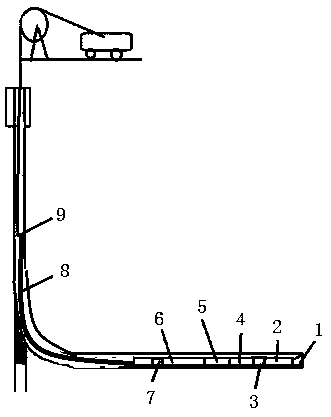
[0028] Step 1: Connect the rigid drill string to the lower end of the coiled tubing 9, the length of the rigid drill string is 600-700m, and then lower the coiled tubing 9 and the rigid drill string to a designated position in the horizontal well through a coiled tubing machine;

[0029] Step 2, under the action of 2-3.5 tons of drilling weight, drill the rigid drill string into 10-20m;

[0030] Step 3: During the drilling process, observe the amount of cuttings returning from the wellhead. If the amount of cuttings returning from...

Embodiment 2

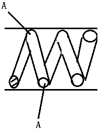
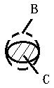
[0035] On the basis of Example 1, in step 4, when the coiled tubing 9 has undergone severe helical bending (such as figure 2 and image 3 shown), repeatedly lift and move the rigid drill string, each time lift the movable rigid drill string 10-15m.

[0036] By lifting the movable rigid drill string, the degree of bending of the spiral tube of the coiled tubing 9 is reduced, and the flow area of ​​the deformed part of the coiled tubing 9 is restored, so that the pressure and displacement of the circulating pump are restored.

Embodiment 3

[0038] On the basis of Example 1, such as figure 1 As shown, the rigid drill string consists of drill bit 1, MWD downhole inclinometer 2, screw rod 3, drill pipe one 4, hydraulic oscillator one 5, weighted drill pipe 6, hydraulic oscillator two 7, drill pipe from bottom to top Two 8 are connected in turn to form. The rigid drill string design given in this example can effectively prolong the length of the sidetracking horizontal section of the coiled tubing gas well and reduce the helical bending degree of the coiled tubing.


PUM


Abstract

The invention provides an application method of a rigid drilling tool for a sidetrack horizontal well by a coiled tubing. The application method comprises the steps that on the basis of the tensile-strength safety factor of 1.4-1.5, the rigid drilling tool with the length of 600-700m is connected with the lower end of the coiled tubing, and the coiled tubing and the rigid drilling tool are loweredto a designated position in a well; under the action of 2-3.5 tons of drilling pressure, drilling is carried out for 10-20m; the return amount of rock debris at a well head is observed, if the returnamount of the rock debris at the wellhead remains unchanged, drilling is carried out continuously, if the rock debris at the wellhead is decreased, the moving drilling tool is lifted up at the wellhead, and the delivery capacity of a circulating pump is increased until all the rock debris at the bottom of the well is taken out; the pump pressure of the circulating pump is observed, if the pump pressure is increased by 1-1.5 Mpa, the moving rigid drilling tool is lifted up repeatedly so that the drilling pressure is transferred to a drill bit, and when drilling is carried out again without footage, the drilling tool is pulled out and drilling of the coiled tubing is finished. According to the application method, the problem that an effective drilling pressure at the bottom of the well gradually decreases which is caused by an existing drilling tool for the sidetrack horizontal well by the coiled tubing with the increase of the horizontal section length of the sidetrack horizontal wellis overcome, and purpose of effectively extending the horizontal section length of side tracking of a coiled tubing gas well is realized.

Description

technical field [0001] The invention belongs to the technical field of oilfield rigid drilling tools, and in particular relates to an application method of a rigid drilling tool for coiled tubing sidetracking horizontal wells. Background technique [0002] Coiled tubing drilling is a technology that uses coiled tubing to complete drilling. Its development and application began in the early 1990s and is a new technology. So far, the number of coiled tubing wells drilled in the United States and Canada accounts for about 80% of the world. Through domestic research and tests in recent years, it is expected that the coiled tubing drilling technology will be one of the main means to tap the potential and increase reserves of many domestic oilfields in the middle and late stages of long-stop wells and low-production and low-efficiency wells. This technology has the characteristics of high efficiency, small footprint and low cost. Combined with underbalanced fluid, it is convenie...

Claims


Application Information

Patent Timeline
Patent Type & Authority Patents(China)
IPC IPC(8): E21B7/04
CPCE21B7/046
Inventor 杨博尹敬军王崇军杨宪利周珊珊牛永博胡久艳
Owner BC P INC CHINA NAT PETROLEUM CORP
Why Eureka
Try Eureka