Radar servo double-machine redundancy switching control system

A control system and dual-machine redundancy technology, applied in the field of servo control, can solve the problems of large amount of wiring, increased equipment amount and development cost, no distinction between large and small signals, etc., so as to reduce maintenance costs in the later period, visualize faults, and simplify wiring. the effect of

Active Publication Date: 2018-10-09
NANJING NRIET IND CORP
View PDF9 Cites 4 Cited by
  • Summary
  • Abstract
  • Description
  • Claims
  • Application Information

AI Technical Summary

Problems solved by technology

In the existing radar servo redundancy scheme, most of the air traffic control secondary radar adopts dual-machine hot backup, that is, dual-motor dual-driver redundant configuration, and hot switching is realized through PLC or PCC, but the secondary radar only has the rotation of the azimuth axis. This scheme requires complex mechanical or electromagnetic clutch devices, and implementing it on a usually dual-axis weather radar will greatly increase the amount of equipment and development costs
In addition, the existing published paper "Airport Weather Radar Servo System Redundancy Design" uses a relay-contactor control system, all of which are connected by wires, with a large amount of wiring, without intelligent control, detection feedback and BIT Function, the switching process does not distinguish between large and small signals, lacks sufficient protection mechanisms, and problems are prone to occur during field application, and it is difficult to diagnose and troubleshoot

Method used


Image

  • Radar servo double-machine redundancy switching control system
  • Radar servo double-machine redundancy switching control system
  • Radar servo double-machine redundancy switching control system

Examples


Embodiment Construction

[0039] The present invention will be described in further detail below in conjunction with the accompanying drawings.

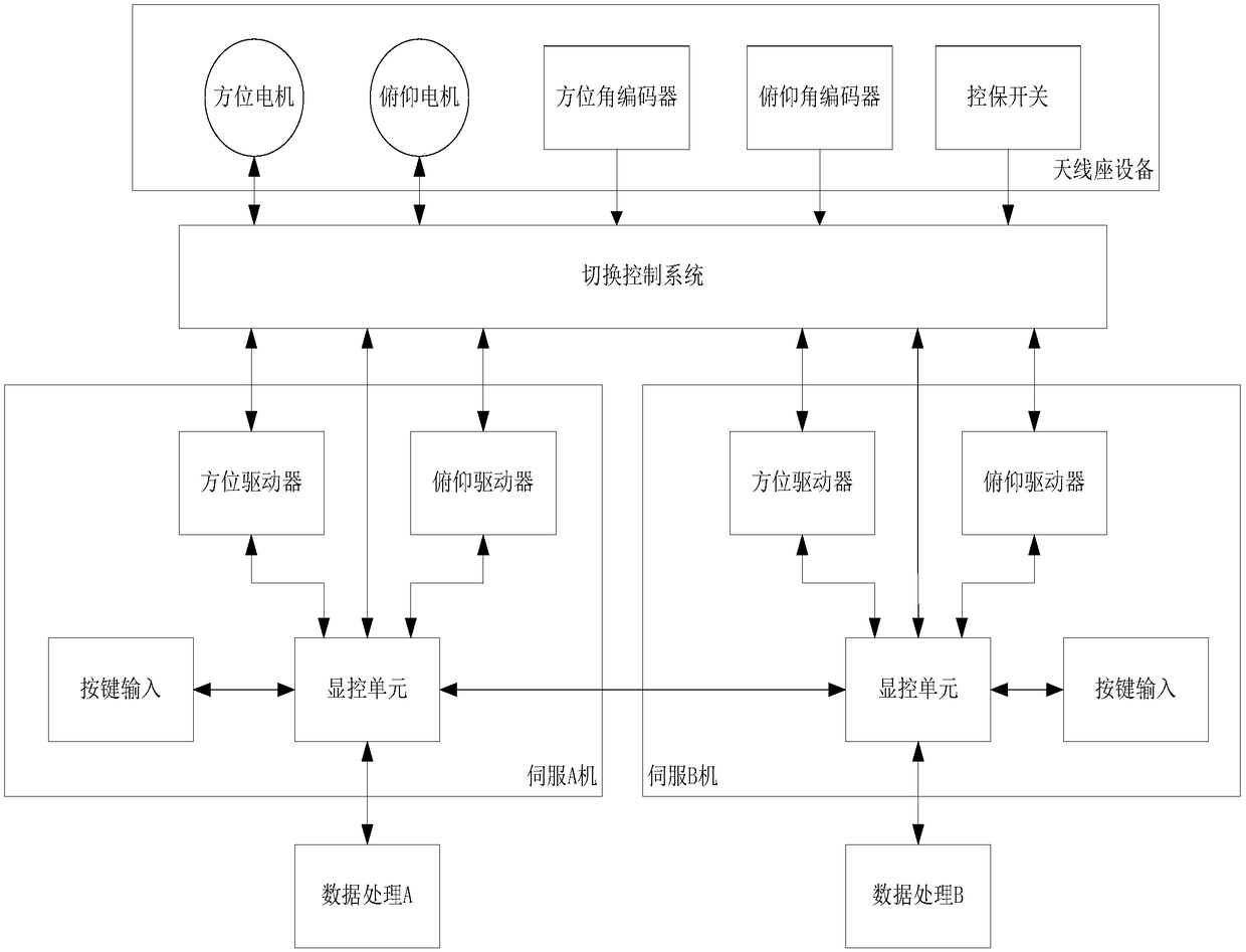
[0040] The dual-machine redundant radar servo system includes the antenna pedestal equipment and the servo extension in the machine room, where the antenna pedestal equipment includes azimuth / pitch servo Motor, azimuth / pitch angle encoder, control switch, servo extension (servo A machine and servo B machine) include control extension and power amplifier extension, control extension includes display and control unit, power amplifier extension includes azimuth / pitch motor driver and power supply. The present invention adopts single-dual-machine hybrid redundant configuration, that is, the antenna base device is a single-machine, and the servo sub-machine is a double-machine redundant scheme.

[0041] Such as figure 1 As shown, the servo system includes two sets of identical servo extensions (A and B), a set of radar servo dual-machine redundant switching contro...


PUM


Abstract

The invention discloses a radar servo double-machine redundancy switching control system. An FPGA main control unit analyzes switching commands of the servo extensions through interface unit analysis,switching control is carried out on a power signal switching unit and a small signal switching unit to ensure that the power signals are switched only after the small signals are completely switched,and the system bit is detected and fed back. The power signal switching unit is driven by a power relay to drive a contactor, and switching control is carried out on the power signals of an antenna base motor. On-line and off-line of the antenna base power equipment is realized. A small signal switching unit is used for driving a signal relay by a driving IC to realize switching of signals in anantenna base. Antenna seat control and protection switch signals and angle encoder signals are simultaneously connected into the two extensions, and synchronous acquisition and display of the public states of the two extensions are guaranteed. An interface unit comprises a control interface for receiving an instruction of the servo extension, a feedback interface for feeding the state of the two extensions back to the servo extension, and a BIT feedback interface for switching the control system.

Description

technical field [0001] The invention relates to a radar servo redundant switching control system, in particular to a radar servo dual-machine redundant switching control system, which belongs to the technical field of servo control. Background technique [0002] Airport weather radar is an important part of the airport's comprehensive meteorological observation system. Air transportation security usually requires weather radar to operate 24 hours a day, which puts high demands on the reliability of the radar servo system. In the existing radar servo redundancy scheme, most of the air traffic control secondary radar adopts dual-machine hot backup, that is, dual-motor dual-driver redundant configuration, and hot switching is realized through PLC or PCC, but the secondary radar only has the rotation of the azimuth axis. This scheme requires complex mechanical or electromagnetic clutch devices, and implementing it on a usually dual-axis weather radar will greatly increase the am...

Claims


Application Information

Patent Timeline
Patent Type & Authority Applications(China)
IPC IPC(8): G05B19/042
CPCG05B19/0421G05B2219/24182
Inventor 徐济安刘新安陈虎王永亮
Owner NANJING NRIET IND CORP
Why Eureka
Try Eureka