Overcurrent protection control circuit

A technology for overcurrent protection and control circuits, applied in the direction of emergency protection circuit devices, electrical components, etc., to achieve the effect of ensuring stability and avoiding damage

Active Publication Date: 2018-10-09
西安矽力杰半导体技术有限公司
View PDF3 Cites 2 Cited by
  • Summary
  • Abstract
  • Description
  • Claims
  • Application Information

AI Technical Summary

Problems solved by technology

[0006] In view of this, the present invention provides an overcurrent protection control circuit, which is used to automatically adjust the off time when overcurrent occurs, and maintain the induct

Method used


Image

  • Overcurrent protection control circuit
  • Overcurrent protection control circuit
  • Overcurrent protection control circuit

Examples


Embodiment Construction

[0030] The present invention is described below based on examples, but the present invention is not limited to these examples. In the following detailed description of the invention, some specific details are set forth in detail. The present invention can be fully understood by those skilled in the art without the description of these detailed parts. In order not to obscure the essence of the present invention, well-known methods, procedures, procedures, components and circuits have not been described in detail.

[0031] Additionally, those of ordinary skill in the art will appreciate that the drawings provided herein are for illustrative purposes and are not necessarily drawn to scale.

[0032] Meanwhile, it should be understood that in the following description, "circuit" refers to a conductive loop formed by at least one element or sub-circuit through electrical connection or electromagnetic connection. When an element or circuit is said to be "connected to" another eleme...


PUM


Abstract

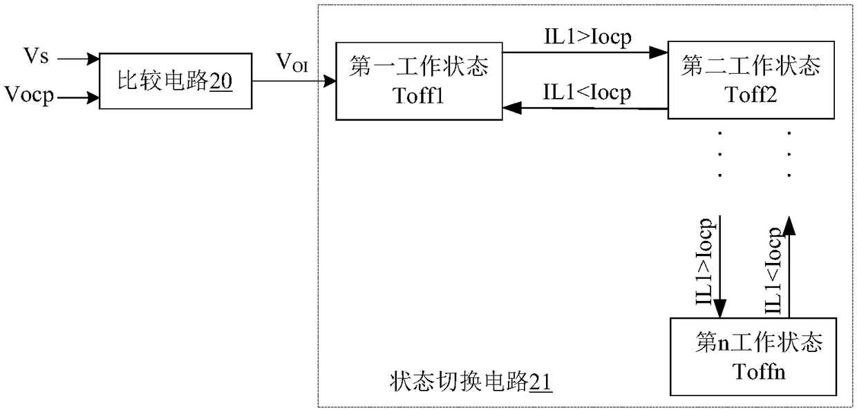
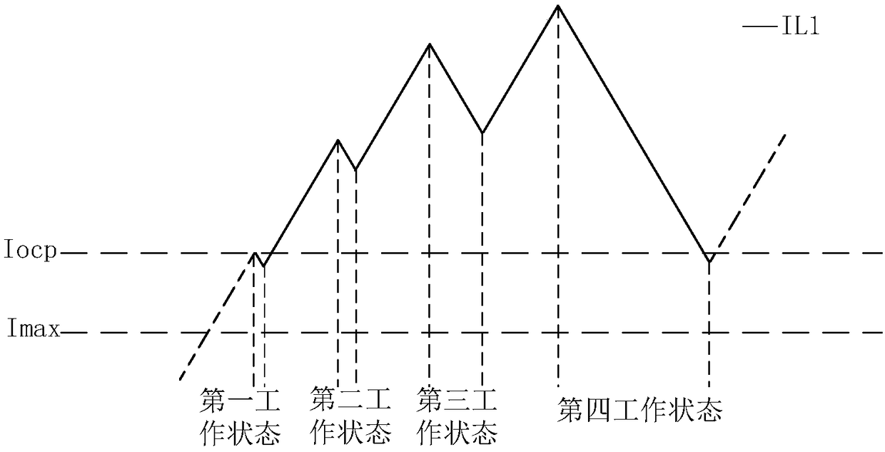
The invention discloses an overcurrent protection control circuit. When an overcurrent occurs in a circuit, a state switching circuit performs state switching according to a magnitude relationship between an inductive current and an overcurrent protection threshold value, so as to adaptively adjust the turn-off time of a power transistor, thus redundant energy has enough time to be absorbed, thereby achieving overcurrent protection, avoiding damage to the circuit, maintaining the inductive current within a predetermined range under normal working conditions, effectively controlling the variation range of the inductive current, and ensuring stability of the system.

Description

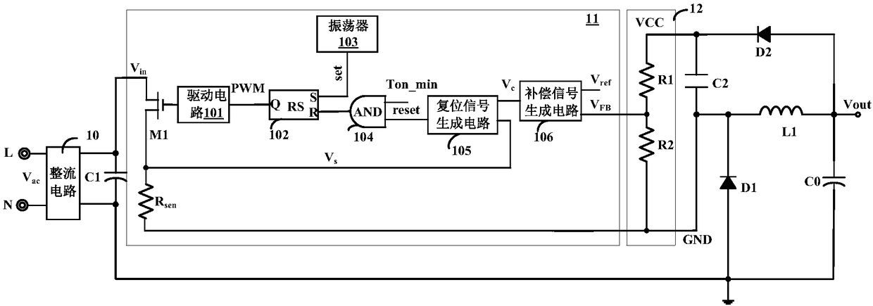
technical field [0001] The invention relates to a power electronic technology, more specifically, to an overcurrent protection control circuit. Background technique [0002] During the application of the switching converter, due to the abnormality of the switching converter, such as a sudden short circuit or overload, the circuit will experience overcurrent. If there is no suitable protection measure, a large amount of energy will be superimposed on the power stage of the switching converter. On the circuit, the energy on the power stage circuit is greater than the maximum energy that it can bear, resulting in damage to the power device. [0003] Such as figure 1 Shown is a circuit schematic diagram of a step-down switching converter in the prior art. The AC input voltage Vac passes through the rectifier circuit 10 and the input capacitor C1 to generate a DC voltage Vin, which is then input to the control circuit 11 . In the step-down switching converter, a sampling resis...

Claims


Application Information

Patent Timeline
IPC IPC(8): H02H7/125
CPCH02H7/1257
Inventor 陈浩李乐李新磊
Owner 西安矽力杰半导体技术有限公司
Why Eureka
Try Eureka