Slide type hand-operated safety chuck convenient for placing, clamping and taking out extended and retracted roll materials

A safety chuck and sliding technology, applied in the field of sliding hand-operated safety chucks, can solve the problems of increased roll swing, decreased product quality, inconvenience in subsequent production, etc., and achieves small circular runout and high use accuracy. , The effect of strong anti-deformation ability

Inactive Publication Date: 2018-10-12
安徽哲乐机电有限公司
View PDF0 Cites 0 Cited by
  • Summary
  • Abstract
  • Description
  • Claims
  • Application Information

AI Technical Summary

Problems solved by technology

[0003] Since the current manual safety chuck is composed of a support end safety chuck and a transmission end safety chuck, and the roller mandrel is clamped between the support end safety chuck and the transmission end safety chuck, the length specifications of the mandrels are different. , and the shortening of the mandrel end due to wear and other reasons, resulting in a gap between the chuck and the mandrel, the torque transmitted from the driving safety chuck to the mandrel will increase, and the winding will be uneven. Or increase the swing range of the roll when unwinding, which will bring inconvenience to the subsequent production and lead to a decline in product quality, etc.

Method used


Image

  • Slide type hand-operated safety chuck convenient for placing, clamping and taking out extended and retracted roll materials
  • Slide type hand-operated safety chuck convenient for placing, clamping and taking out extended and retracted roll materials
  • Slide type hand-operated safety chuck convenient for placing, clamping and taking out extended and retracted roll materials

Examples


Embodiment Construction

[0022] The present invention will be further described below in conjunction with the accompanying drawings.

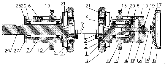
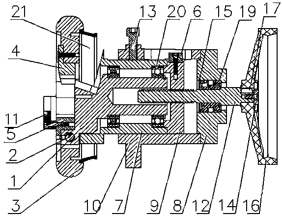
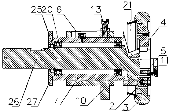
[0023] Such as Figure 1-4 As shown in , a sliding hand-operated safety chuck that is convenient for rewinding and unwinding the roll material, placing the card, releasing it, and taking it out includes a safety chuck at the support end and a safety chuck at the power end, and the short axis 1 groove of the safety chuck at the support end The block and the long axis 26 grooves of the safety chuck at the power end are fitted with the shaft end of the reel mandrel through an insert; Ring 21, the other end of the disc 3 is clamped to the groove block of the short shaft 1 through an insert, the shaft of the short shaft 1 runs through the disc 3 and the rubber ring 21, and the shaft of the short shaft 1 passes through a symmetrically fitted bearing 20 Connect the inner hole of the sliding sleeve 7, one end of the sliding sleeve 7 is connected to the end cover 9, and is set...


PUM


Abstract

The invention discloses a slide type hand-operated safety chuck convenient for placing, clamping and taking out extended and retracted roll materials. The slide type hand-operated safety chuck comprises a supporting end safety chuck and a power end safety chuck, wherein a reel mandrel is blocked and matched between a short shaft groove block of the supporting end safety chuck and a long shaft groove of the power end safety chuck through an insert; a long shaft and a short shaft can be adjusted, so that mounting and using errors can be compensated, and therefore, mandrels of different lengths are adapted; the slide type hand-operated safety chuck is great in bearing capacity, is manufactured from high-quality steel, greatly increases bearing weight through a special structure, is long in use time, is simple in maintenance, adopts blocking hole high-frequency quenching treatment, is convenient in maintenance as parts can be interchanged for use, is high in using precision, enables partsto be wear-resistant by chromium plating, blackening and quenching, is high in part precision, is strong in anti-deforming capability, is small in circular run-out, is high in safety, is dustproof andprevents clamp injury as a circular disc is equipped with a rubber ring, is prevented from dropping as a blocking hole is equipped with an axial positioning ring, is strong in applicability, adopts adetachable blocking hole, replaces different types, and is suitable for a precise high-rotation-speed occasion.

Description

technical field [0001] The invention relates to the technical field of winding and unwinding machinery, in particular to a sliding type manual safety chuck that facilitates the placement and removal of winding and unwinding materials. Background technique [0002] According to the type, the safety chuck can be divided into shaft seat type, flange type, or horizontal installation and vertical installation. The simple, practical and easy-to-install design of the standard safety chuck provides fast, safe, reliable and simple coupling and disengagement operations for frequent actions such as coupling transmission and disengagement. [0003] Since the current manual safety chuck is composed of a support end safety chuck and a transmission end safety chuck, and the roller mandrel is clamped between the support end safety chuck and the transmission end safety chuck, the length specifications of the mandrels are different. , and the shortening of the mandrel end due to wear and oth...

Claims


Application Information

Patent Timeline
IPC IPC(8): B65H75/44
CPCB65H75/44
Inventor 乔印保刘阳
Owner 安徽哲乐机电有限公司
Why Eureka
Try Eureka