Jacketed heat exchanger

A technology of heat exchanger and jacket type, applied in the direction of heat exchanger shell, indirect heat exchanger, heat exchanger fixation, etc., can solve problems such as complex structure of tube sheet, vibration of heat exchange tubes, failure of welding joints, etc., to achieve Guarantee the connection quality, ensure the quality of the weld seam, and prolong the service life

Pending Publication Date: 2018-10-12
ZHANGHUAJI SUZHOU HEAVY EQUIP CO LTD
View PDF1 Cites 2 Cited by
  • Summary
  • Abstract
  • Description
  • Claims
  • Application Information

AI Technical Summary

Problems solved by technology

[0003] Refer to a heat exchanger disclosed in Chinese Patent Application No. 201711044654.4, which includes: a cylinder, a tube sheet, a heat exchange tube and a baffle, the tube sheet is fixedly connected to the cylinder, and the heat exchange tube is arranged on In the cylinder, the two ends of the heat exchange tubes are respectively welded to the tube plate, so that a tube side is formed in the heat exchange tube, and a shell side is formed between the heat exchange tube and the shell, and the medium in the tube side and the medium in the shell side The medium conducts heat transfer. The disadvantages of this type of heat exchanger are: 1. The arrangement of the tube plate makes the structure more complicated; 2. This type of heat exchanger cannot be applied to the powder shell side medium, because after a period of use, the heat exchange tube A certain amount of powder will accumulate on the outer wall surface of the shell, the inner wall surface of the shell, and the surface of the baffle plate. If it is not washed, it will affect the heat exchange performance of the subsequent heat exchanger. It is directly welded to the tube sheets at both ends, so the heat exchange tubes cannot be taken out of the shell for cleaning; 3. Since the medium between the baffles forms a spiral flow, it will cause vibration to the heat exchange tubes, and long-term vibration will cause Fail the weld between the heat exchange tube and the tube sheet, causing leakage

Method used


Image

  • Jacketed heat exchanger
  • Jacketed heat exchanger
  • Jacketed heat exchanger

Examples


Embodiment Construction

[0020] The jacketed heat exchanger of the present invention will be further described in detail below through specific embodiments.

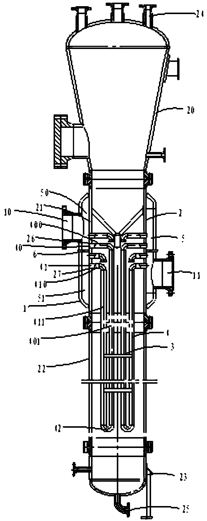
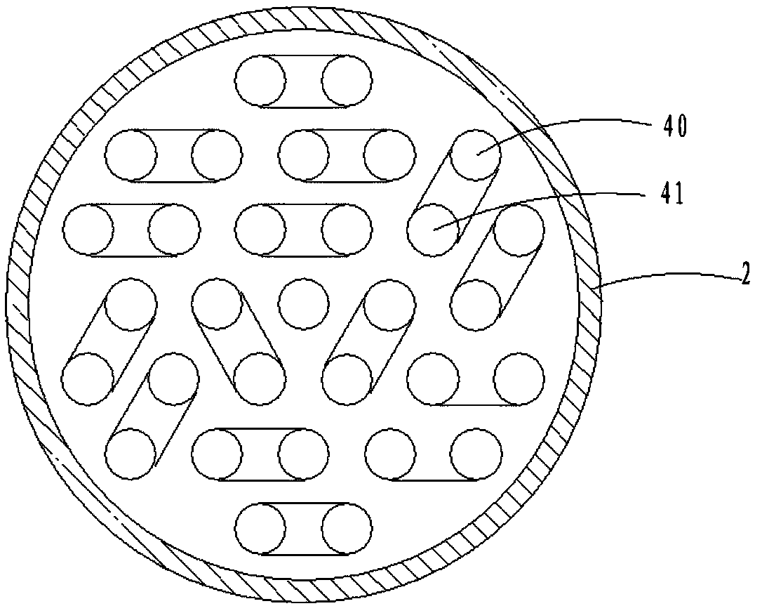
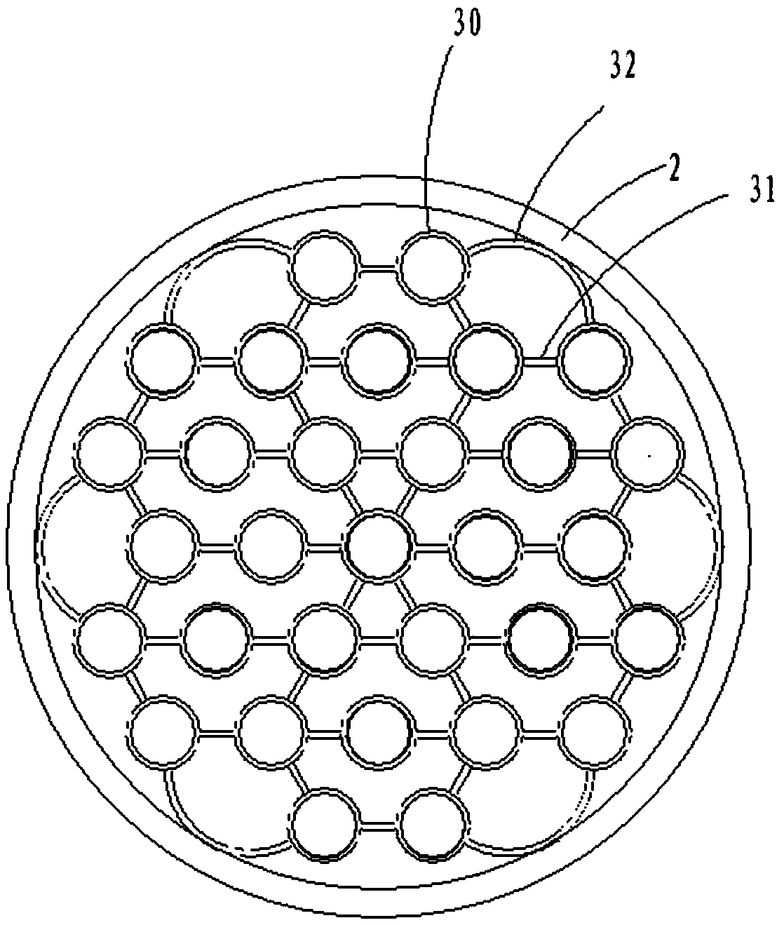
[0021] ginseng Figure 1 to Figure 4 , a jacketed heat exchanger, comprising: an outer shell 1, an inner shell 2, and a number of support mechanisms 3 and a number of heat exchange pipe fittings 4 arranged in the inner shell 2, the outer shell 1 being welded to the outer side of the inner shell 2 , the inner shell 2 includes a first head 20, a first shell section 21, a second shell section 22 and a second head 23, the first head 20 and the first shell section 21 are connected by a flange , the first shell segment 21 and the second shell segment 22 are connected by a flange, the second shell segment 22 and the second head 23 are connected by a flange, and the first head 20 is on the top The width and the lower part are conical, so that the operation space in the inner shell 2 can be enlarged, a jacket layer 5 is formed between the outer shell 1 ...


PUM


Abstract

The invention relates to a jacketed heat exchanger. The jacketed heat exchanger comprises an outer shell and an inner shell and further comprises a plurality of supporting mechanisms and a plurality of heat exchange pipe fittings, all of which are arranged in the inner shell. The outer shell is arranged on the outer side of the inner shell. A jacket layer is formed between the outer shell and theinner shell. A pass partition plate is arranged between the outer shell and the inner shell and divides the jacket layer into a first cavity and a second cavity. The outer shell is provided with a tube pass inlet communicating with the first cavity and a tube pass outlet communicating with the second cavity. Each heat exchange pipe fitting comprises an inlet pipe communicating with the first cavity, an outlet pipe communicating with the second cavity, and a connecting pipe used for connecting the inlet pipe with the outlet pipe. The inner shell is provided with a shell pass inlet and a shell pass outlet. The jacketed heat exchanger is simple in structure and convenient to install; and a jacketed structure is adopted, and the dual effects of outer heating and heat preservation can be achieved.

Description

【Technical field】 [0001] The invention relates to a heat exchanger, in particular to a jacket type heat exchanger. 【Background technique】 [0002] A heat exchanger is an energy-saving device that realizes heat transfer between materials between two or more media at different temperatures. It transfers heat from a higher temperature medium to a lower temperature medium, so that the medium temperature reaches the Specified indicators to meet the needs of process conditions. The heat exchanger industry is mainly concentrated in petroleum, chemical, metallurgy, electric power, shipbuilding, central heating, refrigeration and air conditioning, machinery, food, pharmaceutical and other fields. The domestic heat exchanger industry has made remarkable achievements in research on energy conservation and efficiency enhancement, heat transfer efficiency improvement, heat transfer area reduction, pressure drop reduction, and device thermal strength improvement. [0003] Refer to a hea...

Claims


Application Information

Patent Timeline
Patent Type & Authority Applications(China)
IPC IPC(8): F28D21/00F28F9/00F28F9/013F28F1/00F28F9/26F28F9/12
CPCF28D21/00F28F1/00F28F9/001F28F9/0131F28F9/12F28F9/26F28F2275/06
Inventor 姜玲付冰洋方娟石琦周丽丽
Owner ZHANGHUAJI SUZHOU HEAVY EQUIP CO LTD
Why Eureka
Try Eureka