Quick zero point compensation method for measuring electromagnetic flow

A zero-point compensation and electromagnetic flow technology, applied in the field of electronics, can solve the problems of obstructing current changes, high sensor, large heat generation, etc., to achieve the effect of enhancing zero-point stability, reducing zero-point drift, and ensuring measurement accuracy

Inactive Publication Date: 2018-10-12
CHONGQING CHUANYI AUTOMATION
View PDF6 Cites 4 Cited by
  • Summary
  • Abstract
  • Description
  • Claims
  • Application Information

AI Technical Summary

Problems solved by technology

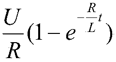
[0002] Electromagnetic flowmeter is an instrument that uses the principle of electromagnetic induction to measure the flow rate of conductive fluid according to the electromotive force induced when the conductive fluid passes through an external magnetic field. During the measurement process, in order to reduce the electrical polarization interference, an alternating magnetic field is usually used. Excitation, but because the coil will bring the inductance effect, the change of the excitation current will follow the working principle of the inductance. When the current changes suddenly, the inductance will generate a reverse electromotive force to hinder the change of the current, so that the current cannot quickly reach the stable state of loading. This state will be subjected to the applied voltage, the resistance and inductance of the coil interacting
[0003] At present, most traditional electromagnetic flowmeters at home and abroad use low-frequency excitation technology to measure in the steady-state region of the excitation current or increase the excitation voltage by improving the excitation circuit when the excitation frequency is increased, forcing the current to increase to a stable state in a short time for measurement; but , since the magnetic field changes when the excitation current is in the rising state, the magnetic field is interfered by various external factors at this time, resulting in the signal being affected by factors such as temperature, time, grounding, eddy current, dielectric impedance, electrode polarization, and signal crosstalk. , can not obtain the same repeatability and linearity as the excitation current in a steady state, which increases the difficulty of signal processing
In order to overcome the problem of stable measurement of signals under short-term excitation state, the existing solutions generally adopt two solutions. The first one is to increase the excitation voltage to force the excitation current to be rapidly increased, but this method consumes a lot of power and generates a lot of heat. , which is not conducive to the use under low power consumption conditions similar to battery power supply, and the heat generation will also bring hidden dangers to the long-term use of the instrument. The second is to use sensors of other structures such as electromagnets to provide magnetic fields, and charge the electromagnets After a short-term excitation, the residual magnetism of the electromagnet is used to provide the magnetic field required for the signal. However, due to the high requirements for the sensor, the corresponding material and process cannot be found in China, and its applicable effect has yet to be tested. Therefore, , a new fast zero point compensation method for electromagnetic flow measurement is needed to improve the signal-to-noise ratio and reduce the zero point drift caused by the influence of the external environment, so as to ensure the measurement accuracy of the instrument in the low flow rate range

Method used


Image

  • Quick zero point compensation method for measuring electromagnetic flow
  • Quick zero point compensation method for measuring electromagnetic flow
  • Quick zero point compensation method for measuring electromagnetic flow

Examples


Embodiment Construction

[0030] Embodiments of the present invention are described below through specific examples, and those skilled in the art can easily understand other advantages and effects of the present invention from the content disclosed in this specification. The present invention can also be implemented or applied through other different specific implementation modes, and various modifications or changes can be made to the details in this specification based on different viewpoints and applications without departing from the spirit of the present invention. It should be noted that, in the case of no conflict, the following embodiments and features in the embodiments can be combined with each other.

[0031] It should be noted that the diagrams provided in the following embodiments are only schematically illustrating the basic ideas of the present invention, and only the components related to the present invention are shown in the diagrams rather than the number, shape and shape of the compo...


PUM


Abstract

The invention provides a quick zero point compensation method for measuring electromagnetic flow. The method comprises the steps of directly collecting zero state signals, and obtaining the offset amount of a signal base line according to the collecting result; according to the offset amount of the signal base line, obtaining an absolute zero point; collecting an actual measurement signal, and compensating for the actual signal through the absolute zero point in real time to complete quick zero point compensation. By means of the quick zero point compensation method, when quick excitation is conducted, interference like orthogonal interference, polarized interference, eddy current interference and common-mode interference is overcome, and the influence of the external environment on the zero points is avoided; through multiple signal control and processing technologies, the signal-to-noise ratio is increased, and zero point drift caused by the influence of the external environment is avoided; through quick compensation for zero point signals, the zero point stability of an instrument is improved, and the measuring precision of the instrument within a flow speed range is guaranteed.

Description

technical field [0001] The invention relates to the field of electronics, in particular to a fast zero point compensation method for electromagnetic flow measurement. Background technique [0002] Electromagnetic flowmeter is an instrument that uses the principle of electromagnetic induction to measure the flow rate of conductive fluid according to the electromotive force induced when the conductive fluid passes through an external magnetic field. During the measurement process, in order to reduce the electrical polarization interference, an alternating magnetic field is usually used. Excitation, but because the coil will bring the inductance effect, the change of the excitation current will follow the working principle of the inductance. When the current changes suddenly, the inductance will generate a reverse electromotive force to hinder the change of the current, so that the current cannot quickly reach the stable state of loading. This state Will be subjected to the app...

Claims


Application Information

Patent Timeline
Patent Type & Authority Applications(China)
IPC IPC(8): G01F25/00
CPCG01F25/10
Inventor 石磊王刚徐科军吴建平许伟梁利平
Owner CHONGQING CHUANYI AUTOMATION
Why Eureka
Try Eureka