
Piezoelectric acoustic wave resonator, piezoelectric acoustic wave filter, duplexer and radio frequency communication module

A piezoelectric acoustic wave and resonator technology, applied in the field of electronic communication technology devices, can solve the problems of increasing the effective electromechanical coupling coefficient of the piezoelectric acoustic wave filter, increasing the manufacturing cost, increasing the volume of the piezoelectric acoustic wave filter, and the like

Active Publication Date: 2018-10-12
SUZHOU HUNTERSUN ELECTRONICS CO LTD
View PDF7 Cites 10 Cited by
  • Summary
  • Abstract
  • Description
  • Claims
  • Application Information

AI Technical Summary

Problems solved by technology

The introduction of inductance / capacitance can increase the effective electromechanical coupling coefficient of the piezoelectric acoustic wave filter and the bandwidth of the piezoelectric acoustic wave filter to a certain extent. The improvement of the filter insertion loss, but at the same time will increase the parasitic effect of the piezoelectric acoustic wave filter, and the piezoelectric acoustic wave will cause some deterioration of the filter performance. In addition, it will also lead to an increase in the volume of the piezoelectric acoustic wave filter and an increase in manufacturing costs.

Method used

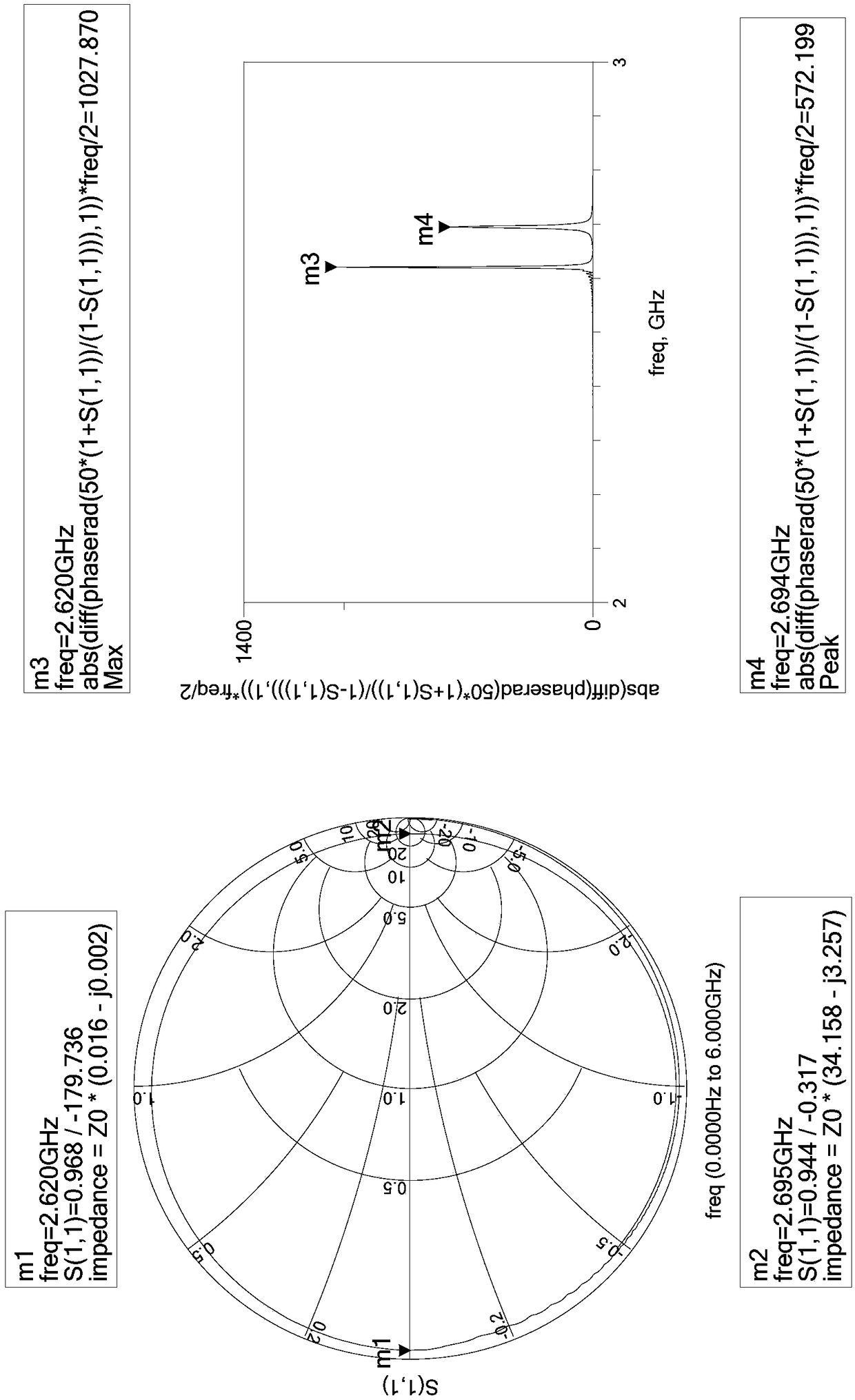
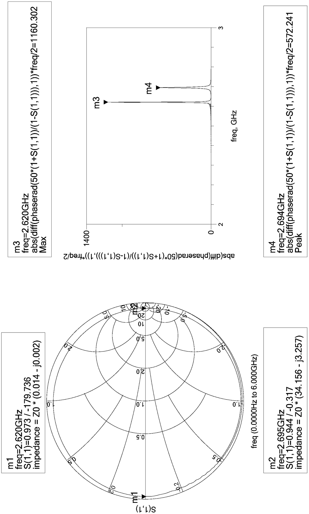
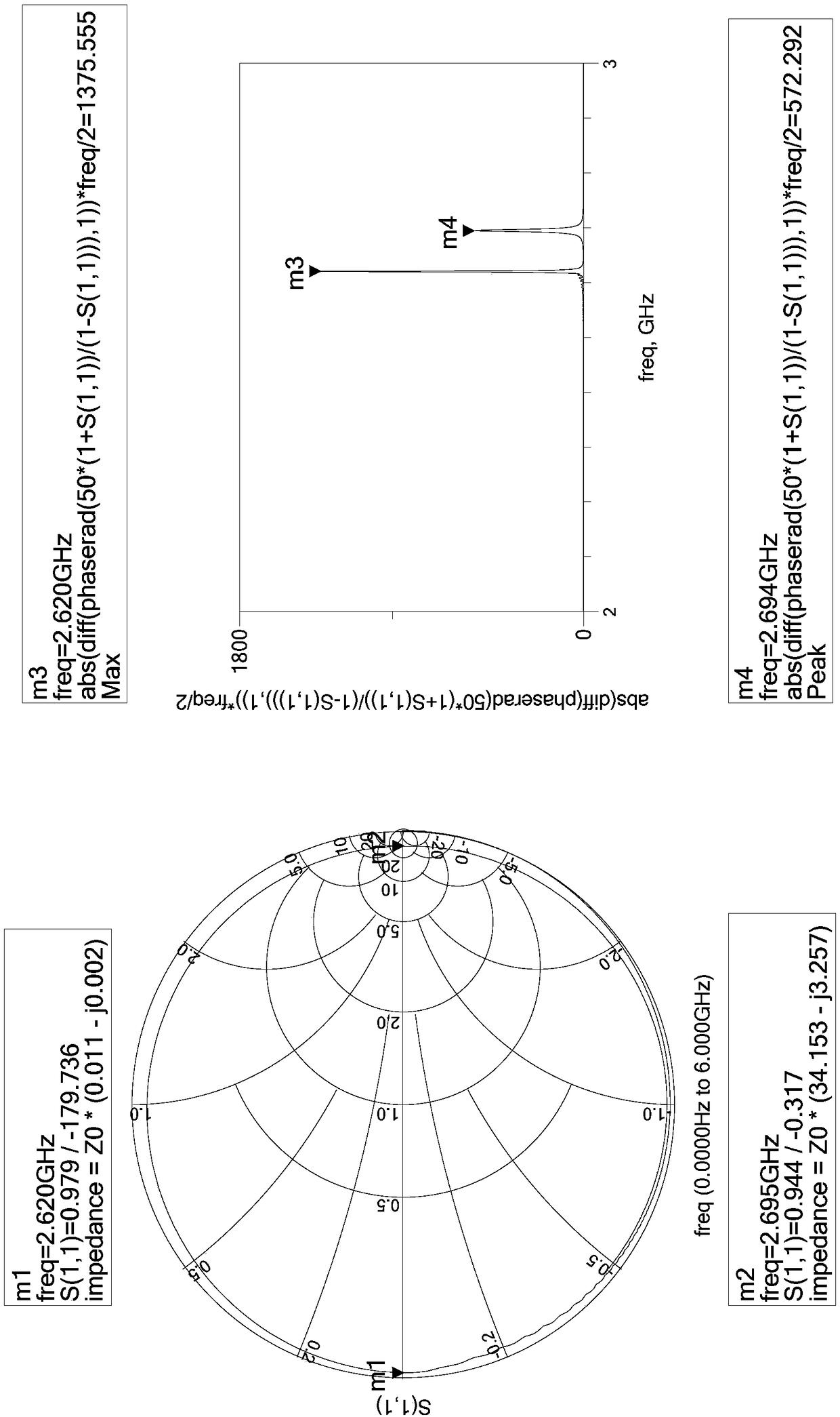

Image

  • Piezoelectric acoustic wave resonator, piezoelectric acoustic wave filter, duplexer and radio frequency communication module
  • Piezoelectric acoustic wave resonator, piezoelectric acoustic wave filter, duplexer and radio frequency communication module
  • Piezoelectric acoustic wave resonator, piezoelectric acoustic wave filter, duplexer and radio frequency communication module

Examples


Embodiment Construction

[0058] In order to better understand and explain the present invention, the present invention will be further described in detail below with reference to the accompanying drawings.

[0059] The invention provides a piezoelectric acoustic wave resonator, the piezoelectric acoustic wave resonator includes an upper electrode layer, a piezoelectric layer, a lower electrode layer and a substrate in order from top to bottom, the upper electrode layer, the piezoelectric layer The overlapping area with the lower electrode layer is the effective working area of ​​the piezoelectric acoustic wave resonator, and the shape of the effective working area is a polygon, wherein:

[0060] The first side in the effective working area corresponds to the input side of the piezoelectric acoustic wave resonator, the second side in the effective working area corresponds to the output side of the piezoelectric acoustic wave resonator, and the effective working area corresponds to the output side of the...


PUM


Abstract

The invention provides a piezoelectric acoustic wave resonator. The shape of an effective working area of the piezoelectric acoustic wave resonator is a polygon, a first side and a second side in theeffective working area correspond to an input side and an output side of the piezoelectric acoustic wave resonator respectively, and an outer frame of the effective working area is defined as a rectangle which can surround the effective working area and has the smallest area where one side coincides with the first side or the second side; one side of the outer frame that coincides with the first side or the second side has a first length, one side of the outer frame that is perpendicular to the side has a second length, and the ratio range of the first length to the second length is 1-4; and the ratio range of the sum of the lengths of the first side and the second side to the circumference of the effective working area is 0.4-0.7, wherein the ratio ranges of the lengths of the first sideand the second side to the circumference of the effective working area are both 0.2-0.35. The invention also provides a piezoelectric acoustic wave filter, a duplexer and a radio frequency communication module. Through the implementation of the invention, the electrical transmission loss of the piezoelectric acoustic wave resonator can be improved, and the insertion loss of the piezoelectric acoustic wave filter can be further improved.

Description

technical field [0001] The invention relates to the field of electronic communication technology devices, in particular to a piezoelectric acoustic wave resonator, a piezoelectric acoustic wave filter, a duplexer and a radio frequency communication module. Background technique [0002] Piezoelectric acoustic wave filter is one of the key components of modern smartphones, and piezoelectric acoustic wave resonator is the core component of piezoelectric acoustic wave resonator. The performance of piezoelectric acoustic wave resonator directly determines the piezoelectric acoustic wave. The pros and cons of filter performance. In the prior art, commonly used piezoelectric acoustic wave resonators include air-gap resonators, bulk silicon back-etched resonators, and Bragg reflection layer resonators. The structure of the piezoelectric acoustic wave resonator will be described below using an air-gap type resonator. Please refer to figure 1 , figure 1 It is a schematic cross-sec...

Claims


Application Information

Patent Timeline
IPC IPC(8): H03H9/17H03H9/54H03H9/70
CPCH03H9/17H03H9/54H03H9/70
Inventor 田晓洁谢恒赖亚明赖志国蔡洵
Owner SUZHOU HUNTERSUN ELECTRONICS CO LTD
Learn More