Microwave ablation antenna

A microwave ablation and antenna technology, applied in the field of tumor treatment, can solve problems such as limited length and diameter, poor impedance matching, and low antenna ablation efficiency, and achieve the effects of improving ablation efficiency, reducing heat generation, and increasing deposition

Inactive Publication Date: 2018-10-16
EAST CHINA UNIV OF SCI & TECH
View PDF3 Cites 5 Cited by
  • Summary
  • Abstract
  • Description
  • Claims
  • Application Information

AI Technical Summary

Problems solved by technology

However, after this treatment, the impedance matching between the antenna and the coaxial cable becomes extremely poor, resulting in low ablation efficiency of the antenna. Since the ablation

Method used


Image

  • Microwave ablation antenna
  • Microwave ablation antenna
  • Microwave ablation antenna

Examples


Embodiment Construction

[0030] Below, in conjunction with the accompanying drawings, preferred embodiments of the present invention are given and described in detail, so that the functions and features of the present invention can be better understood.

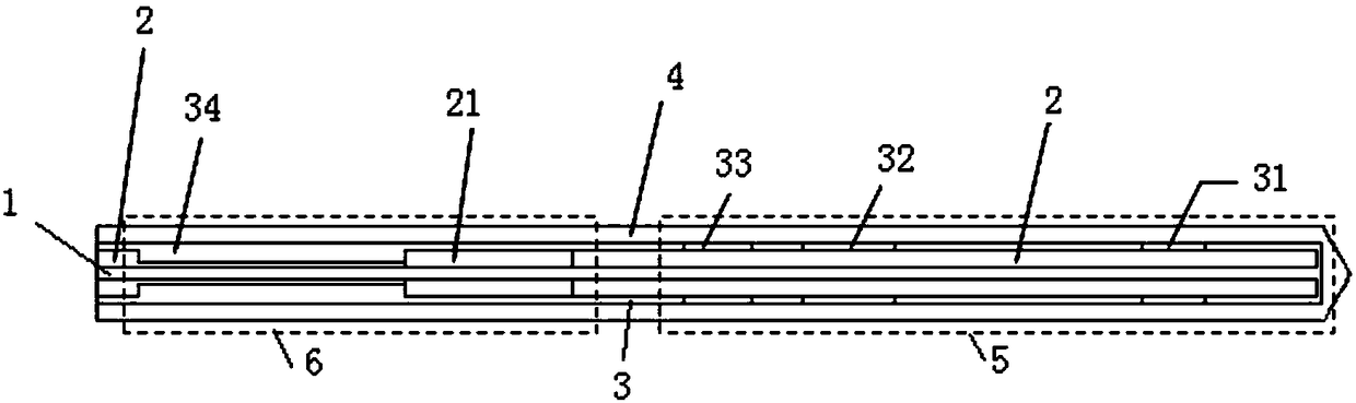
[0031] figure 1 A microwave ablation antenna according to an embodiment of the present invention is shown, which is used to generate a highly spherical ablation area, which is sufficient to completely cover a spherical tumor with a diameter between 3 cm and 5 cm. The antenna has a body, which includes an inner conductor 1, and the outer side of the inner conductor 1 is coated with a dielectric 2, an outer conductor 3 and a Teflon shell 4 in sequence; one end of the body is connected to a coaxial cable along the axial direction, and the other end is An antenna end at which the outer conductor 3 and the inner conductor 1 project beyond the dielectric 2 and are welded to each other.

[0032] Three slits 31, 32, 33 are ring-cut on the outer conductor 3 ...


PUM


Abstract

The invention provides a microwave ablation antenna. The antenna is provided with an antenna body, the antenna body comprises an inner conductor, and the outer side of the inner conductor is sequentially covered with a dielectric, an outer conductor and a shell; the antenna body extends in the axial direction, one end of the antenna body is used for being connected with a coaxial cable, the otherend of the antenna body is an antenna tail end, and the portions, at the antenna tail end, of the outer conductor and the inner conductor protrude out of the dielectric and are welded to each other; three gaps are girdled in the portion, close to the antenna tail end, of the outer conductor; the dielectric in the middle of the antenna body is axially and sequentially provided with a dielectric hollowed-out section and a thickened outer conductor extending inwards from the outer conductor. According to the microwave ablation antenna, the large ablation long diameter and ablation sphericity areobtained through a three gap joint, the ablation radius is increased through the cooperation with a pi matching joint, the comet tail effect can be well eliminated under the condition of not increasing the diameter of the antenna, the ablation sphericity is increased, the sphericity of an ablation area cannot be significantly reduced even if the microwave power is increased, and the large-range high-sphericity ablation area can be formed.

Description

technical field [0001] The invention relates to the field of tumor treatment, in particular to a microwave ablation antenna. Background technique [0002] Microwave ablation refers to the technology of using the thermal effect of microwaves to increase the temperature of diseased tissue, thereby killing human diseased tissue. In recent years, microwave ablation has been rapidly developed as a hyperthermia method capable of precisely killing tumor tissue. In actual clinical operations, with the assistance of CT, ultrasound or MRI imaging methods, the ablation antenna can accurately penetrate the skin to reach the target tissue for ablation. Compared with traditional surgical resection, microwave ablation has many advantages such as small surgical incision, less pain, and shorter postoperative recovery time. [0003] At present, microwave ablation has a remarkable effect in the treatment of tumors with a diameter of less than 3 cm. It can be used to puncture the skin through...

Claims


Application Information

Patent Timeline
IPC IPC(8): A61B18/18
CPCA61B18/1815A61B2018/183A61B2018/1869
Inventor 徐亦帅张兵杨永琴张洪波章文俊余婷婷
Owner EAST CHINA UNIV OF SCI & TECH
Why Eureka
Try Eureka