Decorative wood board paint drying device

A technology for decorating wooden boards and drying devices, which is applied to devices for coating liquid on surfaces, pretreatment surfaces, coatings, etc., can solve problems such as low work efficiency, low drying efficiency, complex structure, etc., and achieves promotion of air circulation. , to ensure the drying effect, the effect of increasing the contact area

Inactive Publication Date: 2018-10-16
陈大祥
View PDF2 Cites 1 Cited by
  • Summary
  • Abstract
  • Description
  • Claims
  • Application Information

AI Technical Summary

Problems solved by technology

The structure of the drying equipment is complicated, it cannot dry multiple boards at the same time, and the work efficiency is low
[0005] The existing drying device cannot dry multiple boards at one time, and the drying efficiency is low; because the temperature control of the boards is relatively strict during the drying process, the heating of each board is uneven, which seriously affects the quality of the boards; some have a one-time The drying device with the function of drying multiple wooden boards is difficult to load and take out the wooden boards, and the surface of the wooden boards is easy to be scratched during the placement and taking process; the mounting seat used to install the wooden boards is not easy to clean thoroughly

Method used


Image

  • Decorative wood board paint drying device
  • Decorative wood board paint drying device

Examples


Embodiment 1

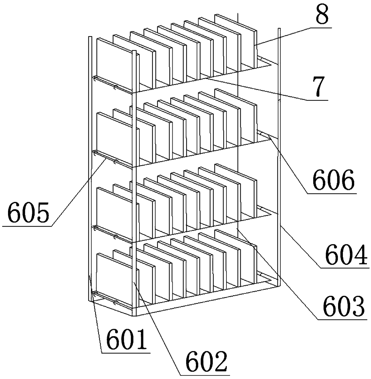
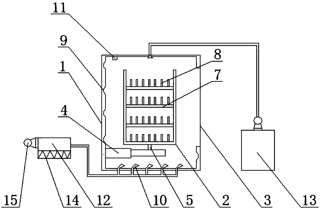
[0026] This embodiment provides a decorative wood paint drying device, which includes a drying box 1 and a placement seat 2. An electric rolling door 3 is provided at the bottom of one side of the drying box 1 for the entry and exit of the placement seat 2. The bottom of the inner wall on one side of the dry box 1 is provided with a hydraulic cylinder 4 for passing the placement seat 2 through the rolling door 3, the placement seat 2 is arranged on the hydraulic cylinder 4, and the placement seat 2 and the hydraulic pressure Between the cylinders 4 is provided a rotating shaft 5 for rotating the placement seat 2 in the vertical direction; Four pillars 604, the first struts 605 that are all arranged between the first pillars 601 and the second pillars 602, the second pillars that are corresponding to the first struts 605 and are all arranged between the third pillars 603 and the fourth pillars 604. Strut 606, the support plate 7 that is movably arranged on the first support 605...

Embodiment 2

[0030] The present embodiment provides a paint drying device on the surface of a wooden board. Compared with Embodiment 1, the difference is that an infrared generator for auxiliary heating is provided in the drying box 1; A dehumidification unit for removing moisture in the hot air flow is provided between the boxes 1, and the dehumidification unit includes two filter screens clamped at the outlet of the heating box 12, and activated carbon filled between the two filter screens; The drying box 1 is provided with a spraying device for cleaning the inside of the drying box 1, and the spraying device includes a spray head arranged on the top of the drying box 1 and an external water source connected to the spray head.

[0031] The infrared generator can assist in heating the wood boards to improve drying efficiency; the dehumidification unit can absorb the water vapor in the hot air flow to prevent the water in the air from affecting the drying effect of the wood boards; 1 The i...


PUM


Abstract

The invention discloses a decorative wood board paint drying device. The bottom of the inner wall of one side of a drying box is provided with a hydraulic used for enabling a placement seat to pass aroller shutter door, the placement seat is arranged on the hydraulic cylinder, and a rotary shaft for enabling the placement seat to rotate in the vertical direction is arranged between the placementseat and the hydraulic cylinder; a plurality of ventilation holes are uniformly distributed on supporting plates, and the upper surfaces of the supporting plates are uniformly provided with parallellyarranged partition plates; the inner wall of the drying box is spirally provided with a spiral air groove for guiding the direction of hot airflow; the bottom of the drying box is uniformly providedwith a plurality of air inlets, and the injection direction of the air inlets is matched with the spiral air groove; and the drying box is internally provided with a visualized fluorescence formaldehyde sensor. The decorative wood board paint drying device is high in drying efficiency and convenient to clean.

Description

technical field [0001] The invention belongs to the technical field of wood board processing, in particular to a decorative wood board paint drying device. Background technique [0002] Wooden boards refer to floors made of wood. At present, wooden boards are dried by drying equipment after being painted. Since the wooden boards need to control the temperature value during the drying process, it is not possible to simultaneously dry multiple boards at the same time. Dry, the drying efficiency is low. [0003] Chinese patent No. CN204182554U discloses a paint drying device on the surface of a wooden board, comprising: a frame, a conveyor belt, a shell, a mercury lamp, a lampshade, an exhaust pipe, and an air intake window, and the conveyor belt is installed on the frame, and the The shell is fixed on the top of the frame by screws, the lampshade is fixed inside the shell by a metal rod, the mercury lamp is installed in the lampshade, one end of the exhaust pipe is connected ...

Claims


Application Information

Patent Timeline
Patent Type & Authority Applications(China)
IPC IPC(8): B05D3/04
CPCB05D3/0413
Inventor 陈大祥
Owner 陈大祥
Why Eureka
Try Eureka