Eureka AIR delivers breakthrough ideas for toughest innovation challenges, trusted by R&D personnel around the world.

A front lower protective device

A protection device, front and lower technology, applied in vehicle parts, transportation and packaging, bumpers, etc., can solve the problems of shock cracking at sheet metal welding, increase the weight of the whole vehicle, increase the difficulty of assembly, etc. Guaranteed connection strength and simple structure

Active Publication Date: 2020-03-24
ANHUI JIANGHUAI AUTOMOBILE GRP CORP LTD
View PDF6 Cites 0 Cited by
  • Summary
  • Abstract
  • Description
  • Claims
  • Application Information

AI Technical Summary

Problems solved by technology

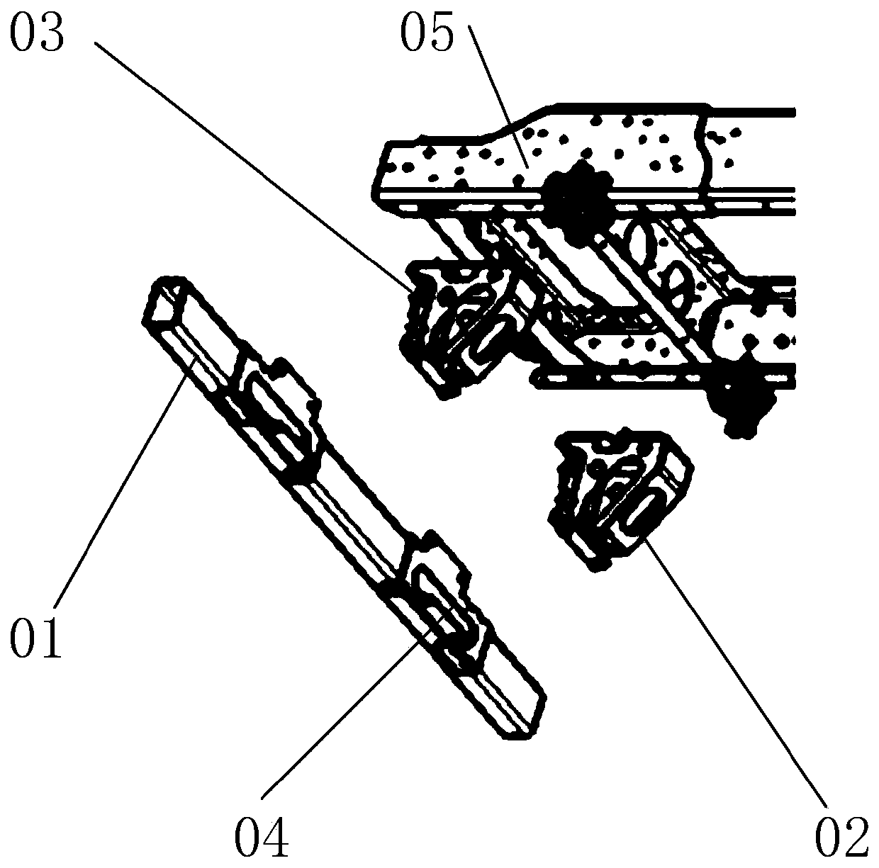
[0004] The anti-collision beam assembly 01 in the prior art is formed by sheet metal stamping and welding. In order to ensure the anti-collision beam assembly 01 assembly, four pieces of sheet metal with the same length are usually welded to form a square anti-collision beam assembly. 01, not only has a complex structure, but also, when it is collided, the sheet metal welding part of the anti-collision beam assembly 01 is vulnerable to vibration and cracking, resulting in damage; at the same time, the welding on the anti-collision beam assembly 01 is used to fix and connect the frame 05 The connecting piece 04, when in use, with the vibration caused by the collision, the anti-collision beam assembly 01 and the connecting frame 05 are also prone to detachment
The above together reduce the service life of the anti-collision beam assembly 01 as a whole; The crossbeam assembly 01 reaches 30kg, and the left mounting support 02 and the right mounting support 03 both exceed 8kg, which are relatively heavy and increase the difficulty of assembly. In summary, the structure of the lower front protection device in the prior art is complex and easy to crack and damage , heavy weight, and difficult assembly. At the same time, due to the heavy weight of the front lower protective device in the prior art, the weight of the whole vehicle will be increased when used, and the fuel consumption of the car will be increased.

Method used


Image

  • A front lower protective device
  • A front lower protective device
  • A front lower protective device

Examples


Embodiment Construction

[0046] Embodiments of the present invention are described in detail below, examples of which are shown in the drawings, wherein the same or similar reference numerals designate the same or similar elements or elements having the same or similar functions throughout. The embodiments described below by referring to the figures are exemplary only for explaining the present invention and should not be construed as limiting the present invention.

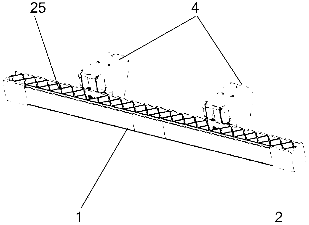
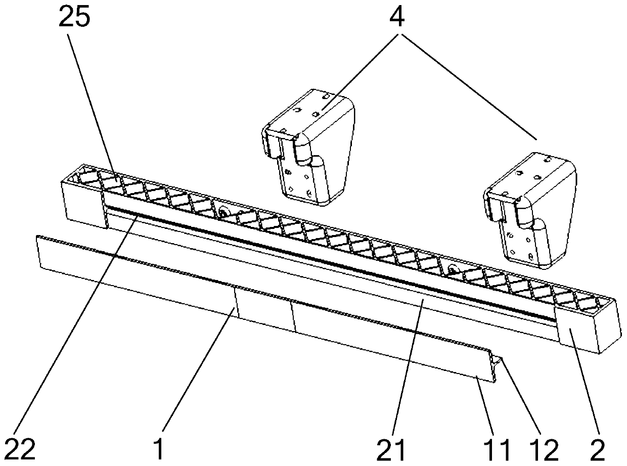
[0047] The embodiment of the present invention provides a front lower protection device, which is mainly used for the front lower part of a commercial vehicle, please refer to figure 2 , image 3 and Figure 4 As shown, the front lower protective device includes T-shaped sheet metal parts 1, plastic beams 2 and embedded bolts 3; The plastic beam 2 is integrally injection molded.

[0048] The present invention adopts the integral injection molding structure of the T-shaped sheet metal part 1, the plastic beam 2 and the embedded bolt 3...


PUM


Abstract

The invention belongs to the technical field of commercial vehicle chassis protection devices, and particularly discloses a front lower portion protection device. The front lower portion protection device comprises T-shaped sheet metal part, a plastic cross beam and embedded bolts. The T-shaped sheet metal part and the embedded bolts are separately and fixedly disposed on two opposite sides of theplastic cross beam and are subjected to integrated injection molding with the plastic cross beam. The front lower portion protection device adopts a structure of which the T-shaped sheet metal part,the plastic cross beam and the embedded bolts are integrally injection-molded, and the T-shaped sheet metal part is directly injection-molded with the plastic cross beam. The structure is simple, andthe connection strength of the T-shaped sheet metal part and the plastic cross beam can be ensured, and damage caused by collision and cracking can be avoided. At the same time, the T-shaped sheet metal part is arranged on one side of the plastic cross beam, when colliding, the T-shaped sheet metal part can provide effective collision contact points to protect the plastic cross beam and prevent the plastic beam from being damaged by collision and cracking. Furthermore, the embedded bolts are directly injection-molded into the plastic cross beam, connecting pieces for installation do not need to be arranged, the mounting structure is simplified, the weight is reduced, and installation is facilitated.

Description

technical field [0001] The invention belongs to the technical field of commercial vehicle chassis protection devices, in particular to a front lower protection device. Background technique [0002] The front lower protective device of commercial vehicles refers to the special front lower protective device or the vehicle body, frame parts or other parts of the vehicle that can have the front lower protective function by virtue of its own shape and characteristics. According to the requirements of the commercial vehicle front lower protection regulations, the front lower protection device must have sufficient blocking force to resist vehicle collision. The specific requirements are that the three collision points P1, P2, and P3 on the front lower protective device need to have strengths of 50%, 100%, and 50% of the maximum total mass of the vehicle or the force of 16t, respectively (see "GB26511 Commercial Vehicle Front Lower Part" for detailed requirements in regulations) Pr...

Claims


Application Information

Patent Timeline
Patent Type & Authority Patents(China)
IPC IPC(8): B60R19/02B60R19/24
CPCB60R19/023B60R19/24
Inventor 梅相全刘洪博郑明敏马建峰徐超黄亮王耘刘永星宋小宁范琼吴向东董野峰王帅
Owner ANHUI JIANGHUAI AUTOMOBILE GRP CORP LTD
Why Eureka
Eureka Blog
Learn More