Very-high-pressure intercooling cycle turbofan engine

A turbofan engine and engine technology, which is applied in the direction of machines/engines, mechanical equipment, gas turbine devices, etc., can solve the problems of reducing engine weight, difficult technical breakthroughs, complicated control systems, etc., to reduce aerodynamic loss and relieve small Reynolds number effect, effect of overall compact structure

Active Publication Date: 2018-10-16
AERO ENGINE ACAD OF CHINA
View PDF4 Cites 7 Cited by
  • Summary
  • Abstract
  • Description
  • Claims
  • Application Information

AI Technical Summary

Problems solved by technology

However, there are still technical barriers that are difficult to overcome in the near future: (1) The temperature before the turbine of the very high pressure thermodynamic cycle is very high, in the order of 2000K to 2200K, which is far beyond the upper temperature limit that the current turbine materials can withstand, so it is necessary to introduce advanced Thermal protection technology to make the turbine work reliably
However, since the very high pressure turbine in this scheme has the outstanding characteristics of being too small in size and not being coaxial with the engine main shaft (does not rotate around the engine main shaft), it is difficult to introduce advanced thermal protection technology to carry out high-strength and reliable (2) Also due to the outstanding characteristics of the very high pressure turbine's small size and not being coaxial with the engine main shaft, the lubrication conditions of the very high pressure shaft are also very harsh, and the technical It is very difficult to break through; (3) The very high pressure compressor, the very high pressure combustor and the very high pressure turbine actually constitute a very high pressure gas generator, and each gas generator has a relatively independent control system. Although the reliability is increased, the control system Too complicated to reduce engine weight

Method used


Image

  • Very-high-pressure intercooling cycle turbofan engine
  • Very-high-pressure intercooling cycle turbofan engine

Examples


Embodiment Construction

[0035] The present disclosure will be further described in detail below in conjunction with the accompanying drawings and embodiments. It should be understood that the specific embodiments described here are only used to explain relevant content, rather than to limit the present disclosure. It should also be noted that, for ease of description, only parts related to the present disclosure are shown in the drawings.

[0036] It should be noted that, in the case of no conflict, the embodiments in the present disclosure and the features in the embodiments can be combined with each other. The present disclosure will be described in detail below with reference to the accompanying drawings and embodiments.

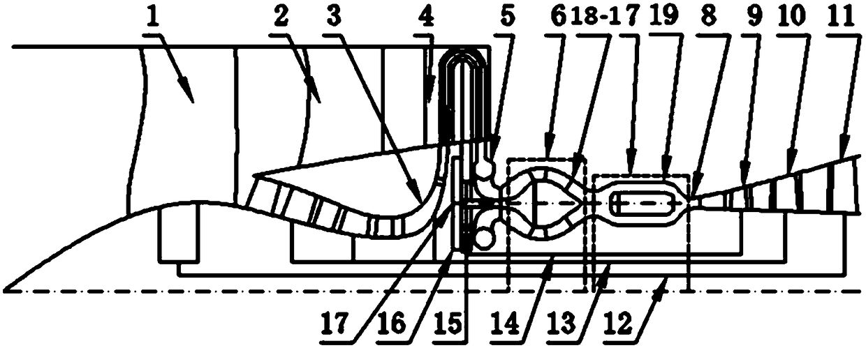
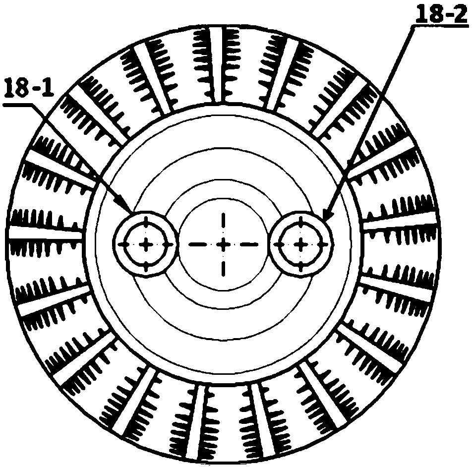
[0037] like Figure 1-2 As shown, the very high pressure intercooled cycle turbofan engine includes fans 1, 2, high pressure compressor 3, intercooler 4, very high pressure compressor 6, combustion chamber 7, circular fan transition section 8, very high pressure turbine 9, Th...


PUM


Abstract

The invention provides a very-high-pressure intercooling cycle turbofan engine. The engine comprises fans, a high-pressure air compressor, an intercooler, a very-high-pressure air compressor, a combustion chamber, a circular rotating fan transition section, a very-high-pressure turbine, a high-pressure turbine, a low-pressure turbine, a low-pressure shaft, a high-pressure shaft and a very-high-pressure shaft. The fans, the high-pressure air compressor, the intercooler, the very-high-pressure air compressor, the combustion chamber, the circular rotating fan transition section, the very-high-pressure turbine, the high-pressure turbine and the low-pressure turbine are connected in sequence. The very-high-pressure turbine drives the very-high-pressure air compressor to operate through the very-high-pressure shaft. The high-pressure turbine drives the high-pressure air compressor to operate through the high-pressure shaft. The low-pressure turbine drives the fans to operate through the low-pressure shaft. The rotation central axis of the very-high-pressure air compressor, and the axis of the combustion chamber are both parallel to the axis of the engine but not coincide with the axis ofthe engine. The high-pressure air compressor is composed of a multi-stage high-load axial flow air compressor and a single-stage high-through-flow centrifugal/oblique flow air compressor.

Description

technical field [0001] The present disclosure relates to the field of aeroengines, in particular to a very high pressure intercooling cycle turbofan engine. Background technique [0002] Lower cruising fuel consumption is one of the most important driving forces for the continuous development of air-breathing high-thrust, large bypass ratio turbofan or paddle fan engines used by military and civilian large and medium-sized transport aircraft. The HEETE (Highly Energy Efficient Turbine Engine) plan of the United States proposes a subversive performance index that the cruising fuel consumption rate of military large and medium-sized transport aircraft will drop by 25% on the basis of the existing level. According to the principle of turbofan or paddle fan engine and the general theory of thermodynamics, the main ways to further significantly reduce the fuel consumption rate of this type of engine are to further increase the bypass ratio to improve propulsion efficiency; or to ...

Claims


Application Information

Patent Timeline
Patent Type & Authority Applications(China)
IPC IPC(8): F02K3/06F02K3/02F02C3/04F02C3/14
Inventor 田晓沛刘若阳杨世豪
Owner AERO ENGINE ACAD OF CHINA
Why Eureka
Try Eureka