Monitoring system of reflective laser foreign object removal device

A monitoring system, a technology for removing foreign objects, applied in the control of using feedback, overhead line/cable equipment, etc., can solve the cost, adaptability, poor equipment maintenance, monitoring and judgment has not risen to the level of automation, lack of foreign object removal process Reliability monitoring and other issues to achieve the effect of increasing reliability and stability, high automation level, and improving automation level

Inactive Publication Date: 2018-10-16
NANJING UNIV OF SCI & TECH
View PDF5 Cites 2 Cited by
  • Summary
  • Abstract
  • Description
  • Claims
  • Application Information

AI Technical Summary

Problems solved by technology

[0003] At present, among the two main methods of foreign matter removal for transmission lines, manual work mostly relies on naked eye observation, and lacks reliability monitoring of the entire foreign matter removal process
Another kind of drone is equipped with a fire-breathing device or uses other mechanical remote control devices to remove foreign objects, etc. In terms of monitoring, there is little feedback on the working status from execution to completion, and the monitoring judgment has not yet risen to the level of automation.
[0004] In terms of communication methods, there are many separate wired communication and wireless communication methods, lack of combination of the two, and a corresponding balance in cost, adaptability, and equipment maintenance.

Method used


Image

  • Monitoring system of reflective laser foreign object removal device
  • Monitoring system of reflective laser foreign object removal device
  • Monitoring system of reflective laser foreign object removal device

Examples


Embodiment Construction

[0022] Attached below Figure 1-4 And embodiment the present invention is described further.

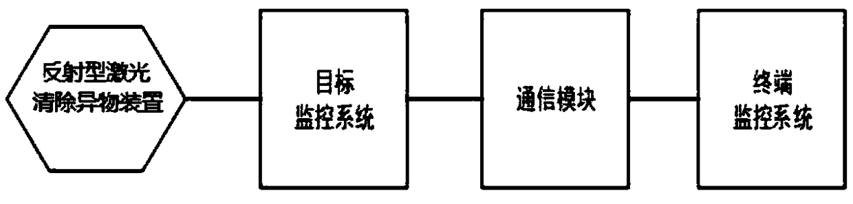
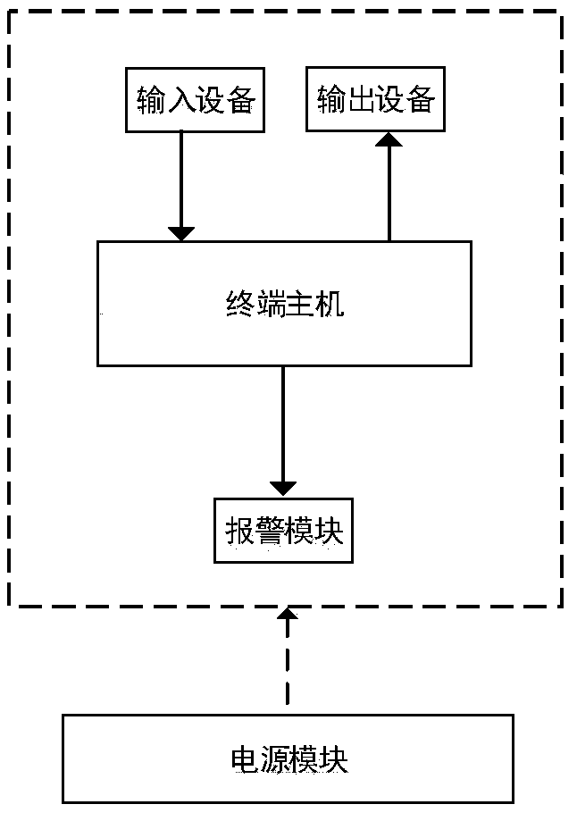
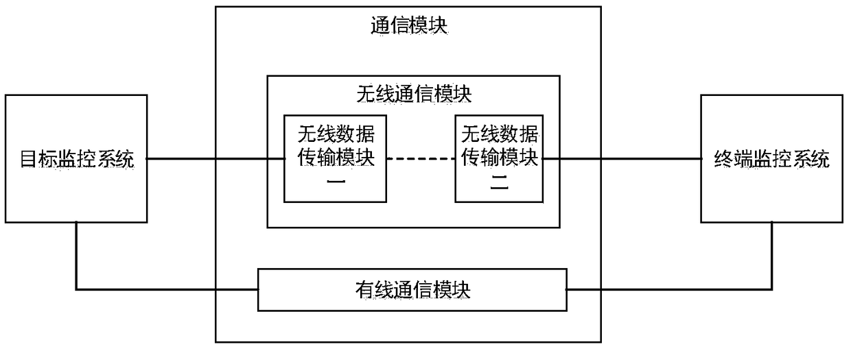
[0023] Such as figure 1 As shown, it is a schematic diagram of the general assembly structure of the monitoring system of the reflective laser foreign matter removal device of the present invention. The monitoring system includes a terminal monitoring system, a communication module, a target monitoring system and a reflective laser foreign matter removal device; Foreign body device. Such as figure 2 As shown, it is a schematic structural diagram of the terminal monitoring system of the reflective laser foreign object removal device monitoring system of the present invention. The terminal monitoring system includes a terminal host, input and output devices, an alarm module, and a power supply module. Such as image 3 As shown, it is a schematic diagram of the structure and connection of the communication module of the monitoring system of the reflective laser foreign matter remov...


PUM


Abstract

The invention discloses a monitoring system of reflective laser foreign object removal device. The monitoring system of reflective laser foreign object removal device comprises a terminal monitoring system, a communication module, a target monitoring system and a reflective laser foreign object removal device. The terminal monitoring system is configured to send a monitoring instruction for the reflective laser foreign object removal device; the control system processes the monitoring instruction into a protocol frame according to the communication protocol requirement, transmits the data through the communication module, or acquires and processes the remote information transmitted by the communication module; the target monitoring system receives the protocol command frame transmitted bythe communication system and performs parsing processing, and transmits the signal to the reflective laser foreign object removal device, when the device feeds back the command information, the corresponding parameter data is transmitted to the communication module according to the communication protocol requirement. The monitoring system, as an auxiliary system of the reflective laser foreign object removal device, can monitor the working state of the device and the foreign matter removal result, perform post-data analysis, overhaul and operation and maintenance, and improve the reliability and stability of working effect of the reflective laser foreign object removal device.

Description

technical field [0001] The invention relates to the monitoring field of removing foreign matter from high-voltage transmission lines in electric power systems, in particular to a monitoring system for a reflective laser removing foreign matter device. Background technique [0002] The reflective laser foreign matter removal device uses a laser with high power and high energy, and its danger monitoring needs to be carried out; the real-time tracking of the foreign matter image requires that the position of the foreign matter recognized by the image is relatively accurate, so as to ensure the high quality of the image captured by the camera and the high precision of the turntable Compared with the stability, the above-mentioned equipment needs accurate cooperation to effectively use the laser to complete the removal of foreign matter on the transmission line. It is necessary to monitor the working status of the device, and it is also conducive to later maintenance and repair. ...

Claims


Application Information

Patent Timeline
Patent Type & Authority Applications(China)
IPC IPC(8): G05D3/12H02G1/02
CPCG05D3/12H02G1/02
Inventor 樊卫华文云郭健李胜郭烨姜珊王艳琴黄紫霄董晟韩宇
Owner NANJING UNIV OF SCI & TECH
Why Eureka
Try Eureka