An Automatic Executing Mechanism Suitable for Residual Stress Relief Device

An automatic execution, residual stress technology, applied in the field of marine ship engineering, can solve the problems of inaccurate alignment of metal surfaces, inaccurate processing position, uneven processing intensity, etc., and achieve the effect of simple structure, good consistency and constant energy

Active Publication Date: 2020-02-07
CHINA SHIP SCIENTIFIC RESEARCH CENTER (THE 702 INSTITUTE OF CHINA SHIPBUILDING INDUSTRY CORPORATION)
View PDF4 Cites 0 Cited by
  • Summary
  • Abstract
  • Description
  • Claims
  • Application Information

AI Technical Summary

Problems solved by technology

[0003] (1) The processing position is inaccurate. In the working state, the impact needle at the front end of the impact gun vibrates at high speed, which causes the entire impact gun to vibrate continuously, making it impossible to accurately align the metal surface to be processed manually, which may cause some metals to be untreated. or excessive processing;
[0004] (2) The treatment intensity is uneven. The stress relief treatment usually requires two to three times of treatment, so that the impact marks all cover the metal surface to be treated. Due to the instability of manual labor, the treatment intensity may be uneven;
[0005] (3) The labor intensity is high and the efficiency is low. Due to the small cross-sectional area of ​​the impact needle at the front end of the impact gun, the metal surface treated by one impact is also very small, which leads to a long time for stress relief treatment, and the correspondingly long working hours. many

Method used


Image

  • An Automatic Executing Mechanism Suitable for Residual Stress Relief Device
  • An Automatic Executing Mechanism Suitable for Residual Stress Relief Device
  • An Automatic Executing Mechanism Suitable for Residual Stress Relief Device

Examples


Embodiment Construction

[0032] Specific embodiments of the present invention will be described below.

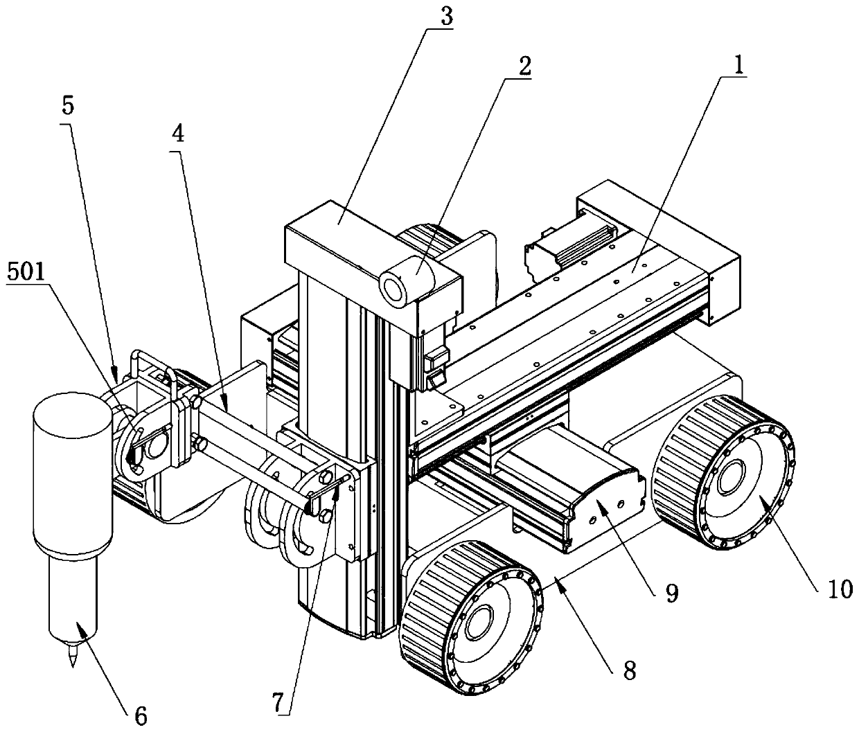
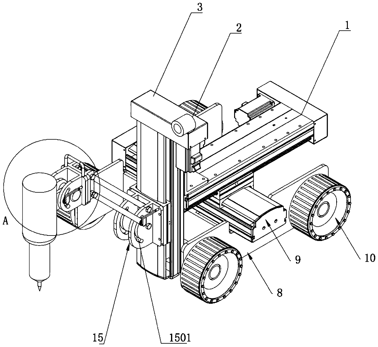
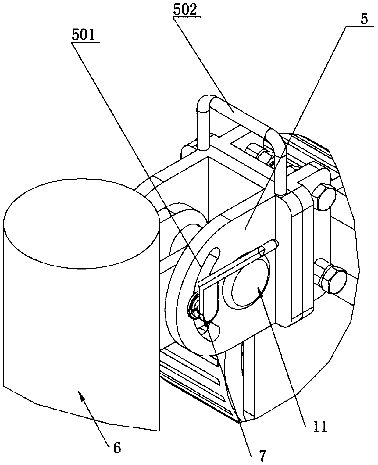
[0033] Such as figure 1 , figure 2 and image 3 As shown, an automatic actuator suitable for a residual stress relief device includes a frame 8, and a self-adsorption mechanism for controlling movement and walking is respectively arranged on both sides of the frame 8. The above-mentioned self-adsorption mechanism includes a wheel outer ring with a magnetic The suction wheels 10 of the block, the inner sides of each suction wheel 10 are controlled to move, turn or locate by driving motors. A three-axis linkage mechanism is arranged on the surface of the frame 8, and the first connecting seat 15 is fixedly connected on the sliding seat of the Z-axis slide table 3 of the three-axis linkage mechanism, and one end of the cantilever 4 is movably connected with the first connecting seat 15, so that the cantilever 4 Make up and down movements relative to the first connecting seat 15; pin the second con...


PUM


Abstract

The invention relates to an automatic executing mechanism suitable for a residual stress eliminating device. The automatic executing mechanism comprises a machine frame, self-adsorption mechanisms used for controlling moving walking are arranged on the two sides of the machine frame correspondingly, a three-axis linkage mechanism is arranged on the surface of the machine frame, a first connectingseat is fixedly connected on a sliding seat of a Z-axis sliding table of the three-axis linkage mechanism, one end of a cantilever is movably connected with the first connecting seat so that the cantilever can move up and down relative to the first connecting seat, the other end of the cantilever is connected with a second connecting seat through pins, the outer side of the second connecting seatis connected with a rotary table through a fastener, and an end seat of an ultrasonic wave output device is in pin joint on the rotary table through a pin shaft. According to the mechanism, the structure is simple, the use is convenient, the mechanism has functions of performing translation in the transverse direction, in the longitudinal direction and the vertical direction and rotating along a transverse axis and a longitudinal axis, the posture and the position of the ultrasonic wave output device can be timely adjusted, and accurate processing of residual stress is achieved.

Description

technical field [0001] The invention relates to the field of ocean ship engineering, in particular to an automatic actuator suitable for a residual stress relief device, which has five degrees of freedom adjustment functions and is equipped with an adsorption system and a monitoring system, and can be used on the upper, lower, and side surfaces of steel structures Suction walking works. Background technique [0002] At present, ships and marine engineering structures are mostly made of high-strength materials. Compared with general materials, high-strength materials have higher sensitivity to welding residual stress. When workpieces are assembled and welded, large welding residual stresses are often generated. reduce structural performance. Therefore, it is of great significance to reduce the residual stress in the structure for ship and ocean engineering structures. Ships and marine engineering structures are large-scale welded structures, with a large number of welds and...

Claims


Application Information

Patent Timeline
Patent Type & Authority Patents(China)
IPC IPC(8): C21D10/00C21D9/50
CPCC21D9/50C21D10/00Y02P10/20
Inventor 张震王永军曹惠星沈永春吴世海张东京刘水清
Owner CHINA SHIP SCIENTIFIC RESEARCH CENTER (THE 702 INSTITUTE OF CHINA SHIPBUILDING INDUSTRY CORPORATION)
Why Eureka
Try Eureka