
Sectional binding apparatus and sectional binding method for rotary targets

A rotating target and segmented technology, applied in ion implantation plating, metal material coating process, coating and other directions, can solve the problems of difficult control of casting uniformity, temperature limitation of binding, and uneven binding, etc. Achieve the effect of improving the bonding rate, reducing deformation, and strong equipment versatility

Pending Publication Date: 2018-10-19
东莞市欧莱溅射靶材有限公司 +1
View PDF0 Cites 9 Cited by
  • Summary
  • Abstract
  • Description
  • Claims
  • Application Information

AI Technical Summary

Problems solved by technology

Some targets will deform when bound for too long
[0004] The contact surface between the rotating target and the back tube is a curved surface, which is different from the planar target. The binding of the rotating target generally uses the rotating target and the back tube as a mold, and a metal layer is required between the target and the back tube as a connecting layer, and the connecting layer is also It is formed by casting, and the metal layer material is generally melted and then cast. However, since the length of the back pipe is 2 to 5 meters long, its binding principle is similar to that of cast pipes. The thinner the pipe wall, the longer the length. Uniformity is more difficult to control
For some targets, the binding temperature is also limited
In order to solve the uneven binding and low welding rate caused by too long binding length, the present invention proposes a segmented binding scheme

Method used


Image

  • Sectional binding apparatus and sectional binding method for rotary targets

Examples


Embodiment 1

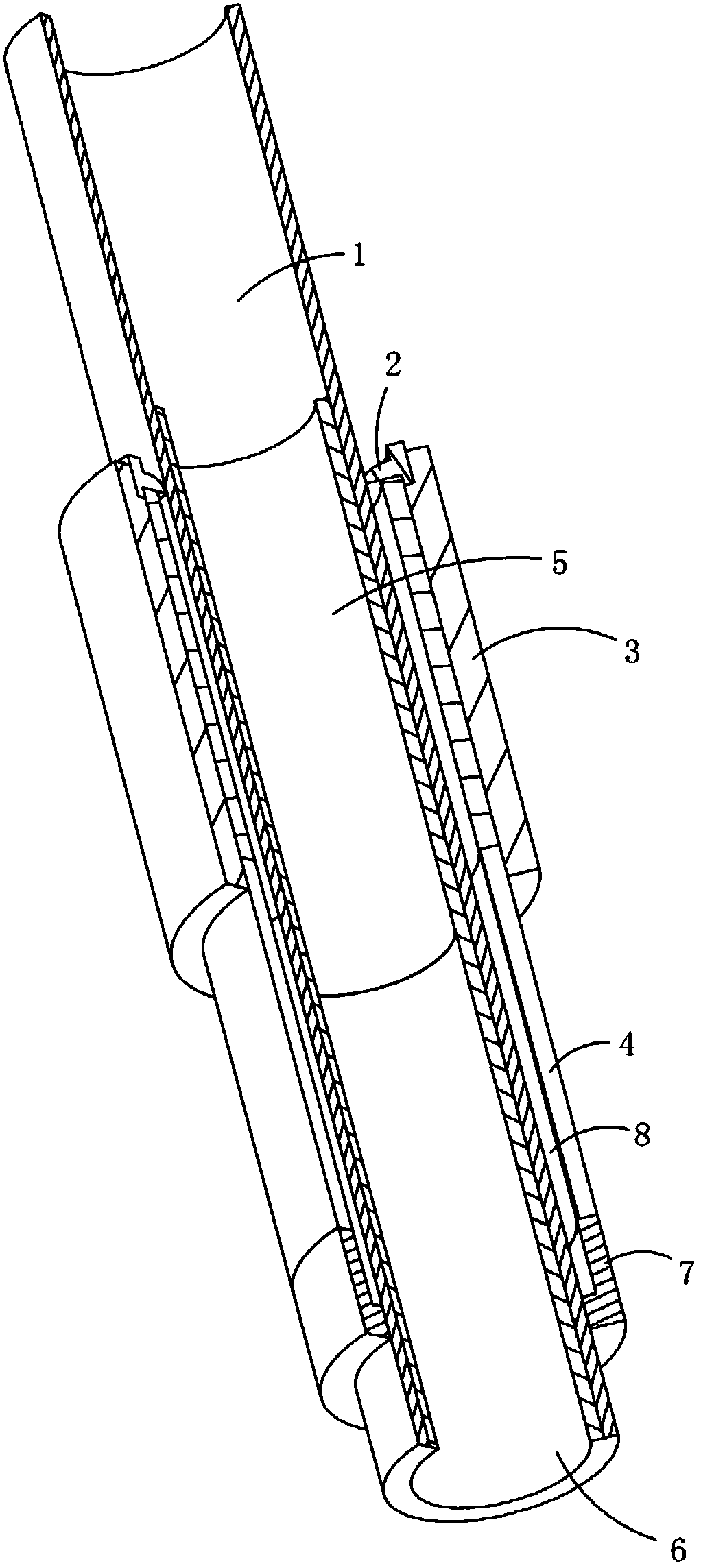
[0043] A rotating target segment binding device, figure 1 As shown, it includes a mobile locator 7 for positioning the back pipe 1, an external heating device 3, a moving guide rod 6 and an internal heating device 5. The lower part of the back pipe 1 is inserted in the mobile locator 7, and the back pipe 1 The lower part is positioned and fixed on the mobile locator 7. Make the back pipe 1 vertically installed on the mobile positioner 7 .

[0044] The bottom of the moving guide rod 6 is connected with a lifting mechanism, which is used to drive the moving guide rod 6 to move up and down. After the back tube 1 is fixed on the mobile positioner 7, the lifting mechanism drives the moving guide rod 6 to be inserted into the back tube 1. After the joints are bound, the lifting mechanism drives the moving guide rod 6 to move out from the back tube 1.

[0045] The mobile positioner 7 is equipped with a vibrating device, which vibrates the back pipe 1 during the casting process, so ...

Embodiment 2

[0053] A method for segmentally binding a rotating target, comprising the following steps:

[0054] a. Install the back tube 1, install the back tube 1 vertically on the mobile locator 7, and use the locator to locate the installation position of the back tube 1 and the starting position of the first metal layer on the back tube, so as to facilitate moving from the back tube The lower part of 1 begins to bind the first metal layer, and the section of the back pipe 1 forming the first metal layer is set with the first metal layer section;

[0055] b, install the external heating device 3, the external heating device 3 is coaxially sleeved on the outer edge of the bottom of the back pipe 1, and the external heating device 3 is fixed on the positioning frame, and the outer wall surface of the back pipe 1 and the external heating device 3 A first casting space in the shape of a ring for casting and forming the first metal layer is formed between them;

[0056] c. Install the inte...


PUM


Abstract

According to the present invention, through the positioning matching of the external heating device and the internal heating device, the multiple sections of the metal layer casting spaces are sequentially formed on the back surface of the back pipe, the multiple sections of the metal layers are sequentially casted on the back surface of the back pipe, and the two adjacent metal layers are connected to form the integration; and with the apparatus and the method, the back pipe molding metal layers with any lengths can be produced, the structure is simple, the number of the heating elements andthe number of various detection elements can be reduced, the adjusting is flexible according to the material of the metal layer, the binding welding rate is improved, the welding quality is improved,the deformation is reduced, the rotary targets with different specifications and different lengths can be produced, the versatility of the device is strong, and the use is convenient.

Description

technical field [0001] The invention relates to the field of target material processing, in particular to a segmented rotating target binding device and a segmented binding method for improving the binding welding rate and welding quality and reducing deformation. Background technique [0002] Magnetron sputtering is widely used, which has promoted the rich development of target products. The nature of many targets determines that they cannot be used directly, and the back tube needs to be bound to the target to meet the installation, conduction and heat dissipation requirements of production equipment. Therefore, the binding technology of the target and the back tube has become a key technology, which directly affects the normal use of the target. [0003] The binding between the rotating target and the back tube is the contact welding of the entire annular surface, which is prone to air bubbles and loosening, which will reduce the performance of the back tube or even fall ...

Claims


Application Information

Patent Timeline
IPC IPC(8): C23C14/34C23C14/35
CPCC23C14/3407C23C14/35Y02E30/10
Inventor 陈明恒文锋
Owner 东莞市欧莱溅射靶材有限公司
Learn More