Emergency device and method applicable to aluminum electrolysis head cell and tail cell
An emergency device, the technology of aluminum electrolysis, applied in the field of aluminum electrolysis equipment, can solve the problems of difficult emergency treatment, difficult current bridging, inability to fully apply the power inlet terminal slot and the power outlet tail slot, etc., to achieve convenient and fast connection , strong overload capacity and easy emergency treatment
- Summary
- Abstract
- Description
- Claims
- Application Information
AI Technical Summary
Problems solved by technology
Method used
Image
Examples
Embodiment 1
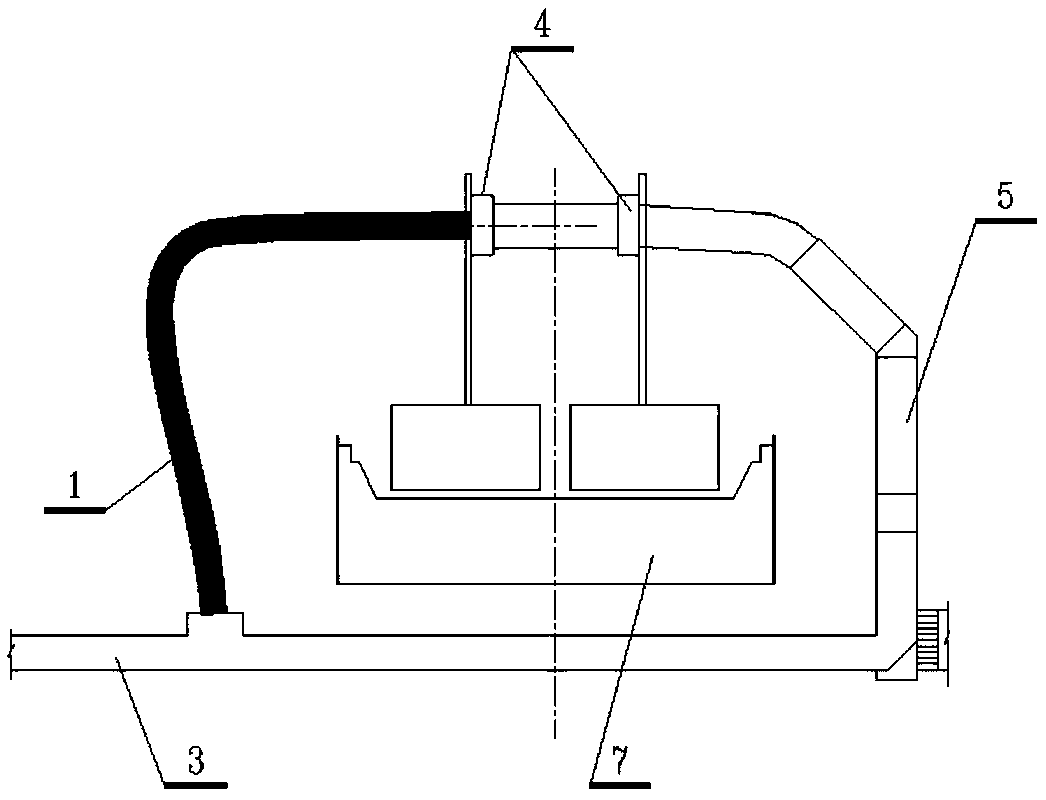
[0026] Embodiment 1: see attached figure 1 , when used in the tail tank of the outlet end of each electrolysis work area, one side of the auxiliary emergency bus 1 is connected to the anode bus 4 of the electrolytic cell 7 at the outlet end by crimping, and the other side is connected by crimping The electric side bus 3, the electrolysis series current can enter the electric side bus 3 through the column bus 5 of the electrolytic tank 7 at the electric outlet, the anode large bus 4 and the auxiliary emergency bus 1.
[0027] The auxiliary emergency busbar 1 is connected to the anode main busbar 4 and the outlet side busbar 3 by crimping, and the crimping method adopts door-shaped clamps or bow-shaped clamps to crimp.
[0028] Such as Figure 5 shown, the bow clamp includes " "type clip 6 and screw 11," The "type clamping piece 6 snaps the anode large busbar 4, the power outlet busbar 3 and the auxiliary emergency busbar 1 into the slot and passes through the screw 11" T...
Embodiment 2
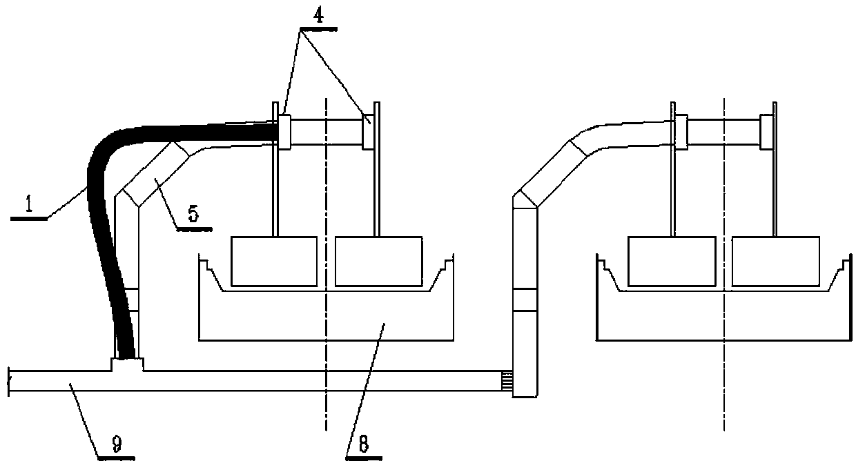
[0030] Embodiment 2: see attached figure 2 , when used in the inlet terminal slot of each electrolysis work area, one side of the auxiliary emergency bus 1 is connected to the anode bus 4 of the electrolytic tank 8 at the inlet end by crimping, and the other side is connected to the aisle bus at the inlet end 9 are connected by crimping, so the electrolysis series current can enter the anode busbar 4 of the electrolysis tank 8 at the power supply end through the aisle bus bar 9 at the power supply end, and finally enter the electrolysis series.
[0031] The auxiliary emergency busbar 1 is connected to the anode busbar 4 and the aisle busbar 9 at the power supply end by crimping, and the crimping method adopts door-shaped clamps or bow-shaped clamps to crimp.
[0032] Such as Figure 5 shown, the bow clamp includes " "type clip 6 and screw 11," The "type clamping piece 6 snaps the anode large busbar 4, the aisle busbar 9 at the power inlet end and the auxiliary emergency ...
Embodiment 3
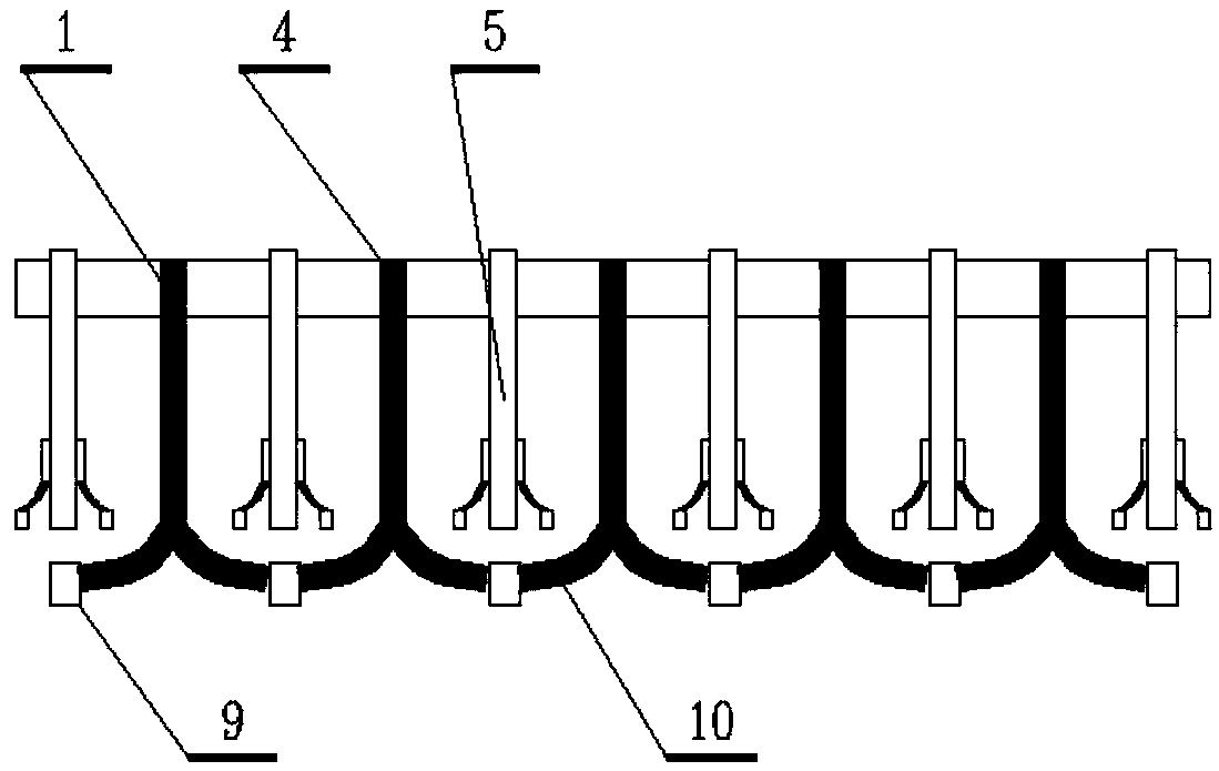
[0034] Embodiment 3: see attachment image 3 , when used in the feed terminal slot of each electrolysis work area, one side of multiple sets of auxiliary emergency bus bars 1 is connected to the anode bus bar 4 of the feed end electrolyzer 8 by crimping, and the other side is connected by a transfer bus bar 10 is connected to the aisle busbar 9 at the power supply end by crimping, so the electrolytic series current can enter the anode busbar 4 of the electrolytic tank 8 at the power supply end through the aisle busbar 9 at the power supply end, and finally enter the electrolysis series. The transfer busbar 10 can lead the current of the two aisle busbars 9 at the feeder end into an auxiliary emergency busbar 1 .
[0035] The auxiliary emergency bus 1 adopts multiple groups, and one end of the multi-group auxiliary emergency bus 1 is connected to the anode large bus 4 of the electrolytic cell 8 at the power inlet end through the crimping method adopted in Embodiment 1 and Embod...
PUM
 Abstract
Description
Claims
Application Information
 - R&D
- Intellectual Property
- Life Sciences
- Materials
- Tech Scout
- Unparalleled Data Quality
- Higher Quality Content
- 60% Fewer Hallucinations
Browse by: Latest US Patents, China's latest patents, Technical Efficacy Thesaurus, Application Domain, Technology Topic, Popular Technical Reports.
© 2025 PatSnap. All rights reserved.Legal|Privacy policy|Modern Slavery Act Transparency Statement|Sitemap|About US| Contact US: help@patsnap.com


