
Automatic silk reeling machine steam pipeline device and its control technology

A steam pipe and silk reeling locomotive head technology, applied in the field of locomotive threading, can solve problems such as difficult threading, small temperature difference, etc., and achieve the effect of improving accuracy, improving adaptability, and expanding stand capacity

Active Publication Date: 2020-09-01
四川省丝绸工程技术研究中心 +1
View PDF8 Cites 0 Cited by
  • Summary
  • Abstract
  • Description
  • Claims
  • Application Information

AI Technical Summary

Problems solved by technology

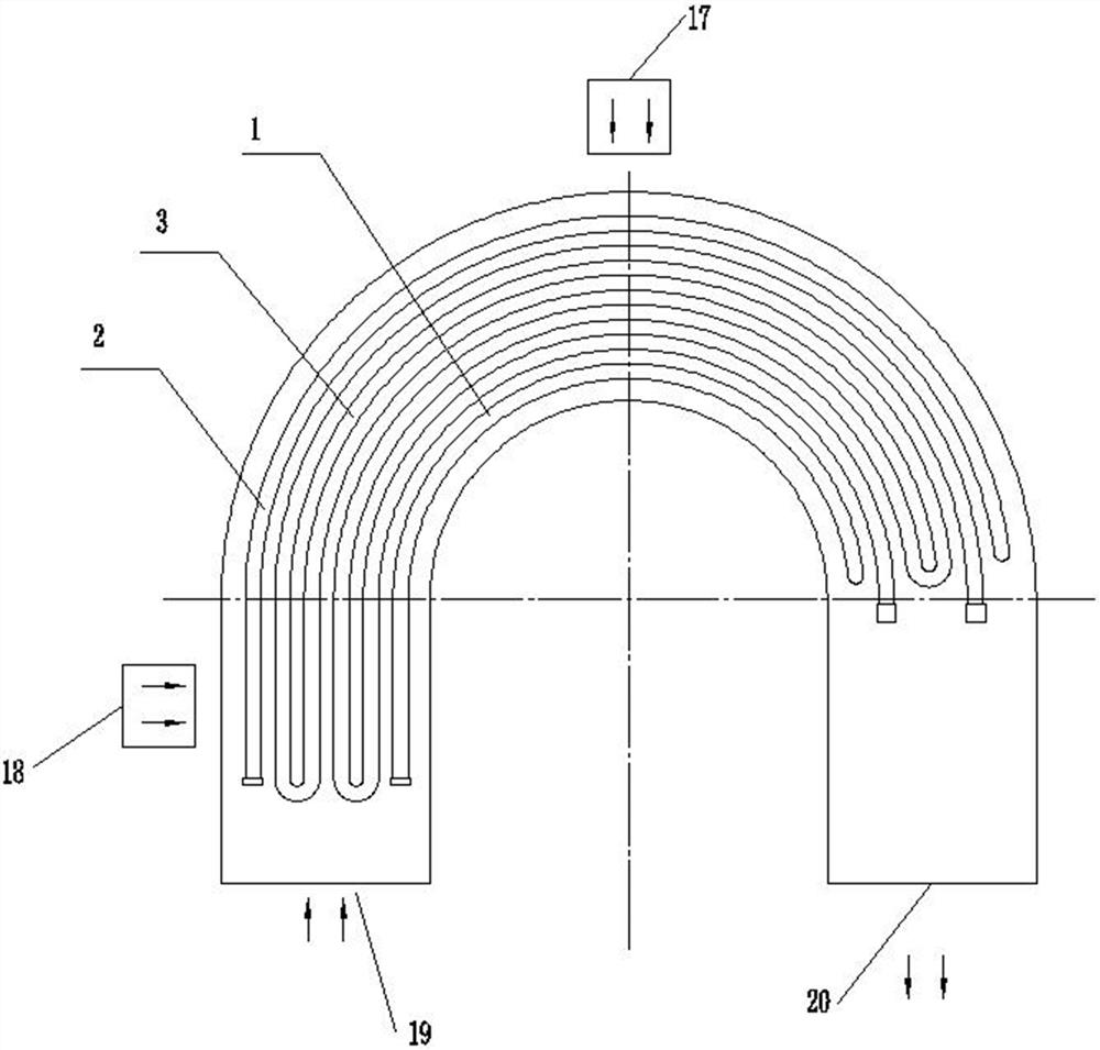
[0019] The purpose of the present invention is to design the automatic silk reeling locomotive head threading steam pipeline device and its control process. The steam pipeline device adopts a segmented design structure to control the total amount of steam to solve the problem of high temperature in the prior art. The shortcoming that the temperature difference between the low temperature zone and the low temperature zone is too small is not easy to thread, which can effectively meet the temperature of the high temperature zone of the Suoxu pot in the required high temperature range, and the low temperature zone can also be in the required low temperature range, so that the cable in the Suoxu pot Xutang can meet the temperature conditions of Suoxu; the control process combines various technologies such as physical data acquisition and electrical control to automatically control its equipment and process data, so as to improve the accuracy of temperature control and improve the quality of equipment and equipment. Process performance

Method used


Image

  • Automatic silk reeling machine steam pipeline device and its control technology
  • Automatic silk reeling machine steam pipeline device and its control technology
  • Automatic silk reeling machine steam pipeline device and its control technology

Examples


Embodiment 1

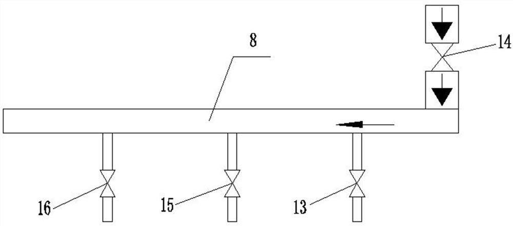
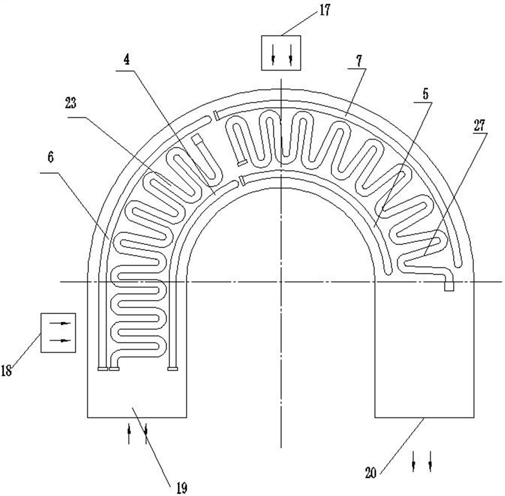
[0053] The invention proposes a steam pipeline device for an automatic silk reeling machine, which adopts a segmented design structure for controlling the total amount of steam, which solves the disadvantages of the prior art that the temperature difference between the high temperature zone and the low temperature zone is small and difficult to track, and can effectively Satisfied that the temperature of the high temperature zone of the Suoxu pot is in the required high temperature range, and the low temperature zone can also be in the required low temperature range, so that the Suoxu soup in the Suoxu pot can meet the temperature conditions of Suoxu, such as Figure 3-5 As shown, the following arrangement structure is adopted in particular: the inner hole pipe 1, the outer hole pipe 2, the blind pipe 3, the steam main pipe 8, the steam main valve 14, which are arranged at the Suoxu pot of the headstock, the inner hole pipe 1 and the outer hole pipe The orifice tubes 2 are comp...

Embodiment 2

[0056] This embodiment is further optimized on the basis of the above-mentioned embodiments, further to better realize the automatic silk reeling machine steam pipeline device of the present invention, such as Figure 3-5As shown, the following arrangement method is adopted in particular: the inner hole tube 1 is provided with the inner hole tube 4 of the high temperature temperature control part and the inner hole tube 5 of the low temperature temperature control part respectively connected with the steam main pipe 8, and the inner hole tube 4 of the high temperature temperature control part passes through The valve group of the high temperature temperature control part is connected with the steam main pipe, and the inner hole pipe 5 of the low temperature temperature control part is connected with the steam main pipe through the valve group of the low temperature temperature control part.

[0057] When designed and used, the inner hole tube 1 is composed of the inner hole tub...

Embodiment 3

[0059] This embodiment is further optimized on the basis of any of the above embodiments, further to better realize the automatic silk reeling machine steam pipeline device of the present invention, such as Figure 3-5 As shown, the following arrangement method is adopted in particular: the outer hole tube 2 is provided with the outer hole tube 6 of the high temperature temperature control part and the outer hole tube 7 of the low temperature temperature control part respectively connected with the steam main pipe 8, and the outer hole tube 7 of the high temperature temperature control part The pipe 6 is connected to the steam main pipe through the valve group of the high temperature temperature control part, and the outer hole pipe 7 of the low temperature temperature control part is connected to the steam main pipe through the valve group of the low temperature temperature control part.

[0060] When designed and used, the outer hole tube 2 is composed of the outer hole tube ...


PUM


Abstract

The invention discloses a steam pipeline device of an automatic silk reeling machine and a control process of the steam pipeline device. The steam pipeline device comprises an inner perforated pipe, an outer perforated pipe, a blind pipe, a steam manifold and a steam main valve which are arranged at an end groping basin, wherein each of the inner perforated pipe and the outer perforated pipe comprises two perforated pipe sections controlling steam supply quantity. The control process includes: real-time temperature is collected through a temperature sensor and compared with set temperature, the openness of an electric valve is calculated through the valve openness feedback signal of the electric valve and PID operation, and a PLC outputs to control the openness of the electric valve so asto adjust pipeline steam pressure. The steam pipeline device has the advantages that total steam quantity is controlled through the sectioned design structure, the requirements that the temperature ofthe high temperature area of the end groping basin is located in the required high temperature interval and the temperature of the low temperature area of the end groping basin is located in the required low temperature interval can be satisfied effectively, and accordingly the end groping hot water in the end groping basin can meet the end groping temperature condition.

Description

technical field [0001] The invention relates to the field of locomotive threading technology and the like, in particular to an automatic silk reeling locomotive threading steam pipeline device and its control process. Background technique [0002] The automatic reeling machine is the key equipment for raw silk processing, which draws out cocoon silk and assembles it into raw silk. Raw silk production is a traditional advantageous project in my country, and the automatic silk reeling machine produced in my country represents the most advanced level in the world. The automatic silk reeling machine is composed of a locomotive and a body. Generally, one silk reeling machine has 400 threads for the body, and each group is equipped with a locomotive (a cable threading mechanism) at both ends. At present, my country's relatively advanced automatic silk reeling machine is the leader of Hangzhou Textile Machinery Factory. [0003] Thread silkworm cocoons (including boiled cocoons, ...

Claims


Application Information

Patent Timeline
Patent Type & Authority Patents(China)
IPC IPC(8): D01B7/04
CPCD01B7/04
Inventor 陈祥平程明卜献鸿刘季平任强胜陈伍彪
Owner 四川省丝绸工程技术研究中心
Learn More