Uplift pile and construction method thereof

A technology of anti-pull piles and pile bodies, which is applied in the direction of sheet pile walls, foundation structure engineering, protection devices, etc., and can solve the problems of the joints of pile bodies being broken, corroded, bearing pressure and limited compression and pullout capabilities, etc. Achieve the effects of strengthening the strength of the connection, simplifying the process steps, and improving the pull-out resistance

Pending Publication Date: 2018-10-19
JINLING INST OF TECH
View PDF29 Cites 4 Cited by
  • Summary
  • Abstract
  • Description
  • Claims
  • Application Information

AI Technical Summary

Problems solved by technology

Since the pile body is buried under the ground for a long time, metal fasteners such as welds or bolts are prone to corrosion due to water vapor, destroying the connection strength between piles, thereby reducing the pullout resistance of uplift piles
[0003] The Chinese invention patent with the publication number CN100585092C discloses a pile-forming method for compressive and uplift-resistant pile foundations. Aiming at the technical problems of the straight columnar cast-in-situ piles, which have limited pressure bearing and compressive and pullout capabilities, the specification discloses the following: Technical solution: the main body of the pile foundation is made of steel bars and concrete. The steel bars expand outwards at the bottom of the main body of the pile foundation, forming a large-headed chassis with a radial dimension larger than the main body of the pile foundation at the bottom of the main body of the pile foundation. However, the piles of this structure The foundation needs to process multiple through holes on the pipe wall of the steel pipe formwork for placing steel bars, and when the steel pipe formwork is driven into the foundation, the steel bars need to be hit twice to expose the steel bar membrane, and the construction process is more cumbersome
[0004] The Chinese invention patent application with publication number 105133599A discloses an uplift-resistant pile. Aiming at the technical problem that the friction force between the pile body and the surrounding soil is only provided by the outer wall of the pile body, and the pullout resistance capacity is not high, it discloses the following in its specification: Technical solution; by setting multiple steps on the pile body, the pile body can obtain good pullout resistance in each soil layer, but the pile body is a solid structure, and the connection between two adjacent pile bodies is through Connecting holes are provided in the length direction of the pile body, and the pile body of such a structure is difficult to manufacture, and if combined with the pouring method disclosed by the publication number CN100585092C, there will be a problem of connection strength between the pile bodies, which will be due to the The connection strength of the pile body is much smaller than the pullout force of the pile body, and it is prone to the defect that the pile body is pulled apart or even the connection between the pile body is pulled apart

Method used


Image

  • Uplift pile and construction method thereof
  • Uplift pile and construction method thereof
  • Uplift pile and construction method thereof

Examples


no. 1 example

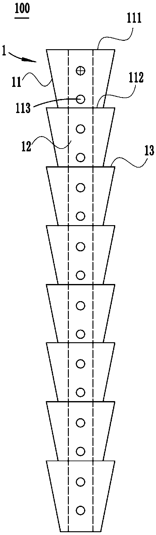
[0032] The first embodiment: according to the attached figure 1 As shown, the uplift pile 100 includes a pile body 1 extending in the vertical direction, a plurality of pile bodies 11 forming the pile body 1 , and a cement slurry flow channel 12 passing through the pile body 1 . Wherein, a plurality of pile bodies 11 are fixedly arranged in sequence. In this example, each pile body 11 has a first end 111 located at the upper part and a second end 112 located at the lower part, and the transverse width of the first end 111 is greater than the transverse width of the second end 112. The second end 112 of one pile body 11 among the pile bodies 11 is fixedly arranged with the first end portion 111 of the other pile body 11 . The joints of the first and second ends protrude outward to form the occlusal portion / barb portion 13 where the uplift pile 100 and the building soil layer are occluded. In other embodiments, a plurality of pile bodies 11 integrally form the pile body 1; two...

no. 2 example

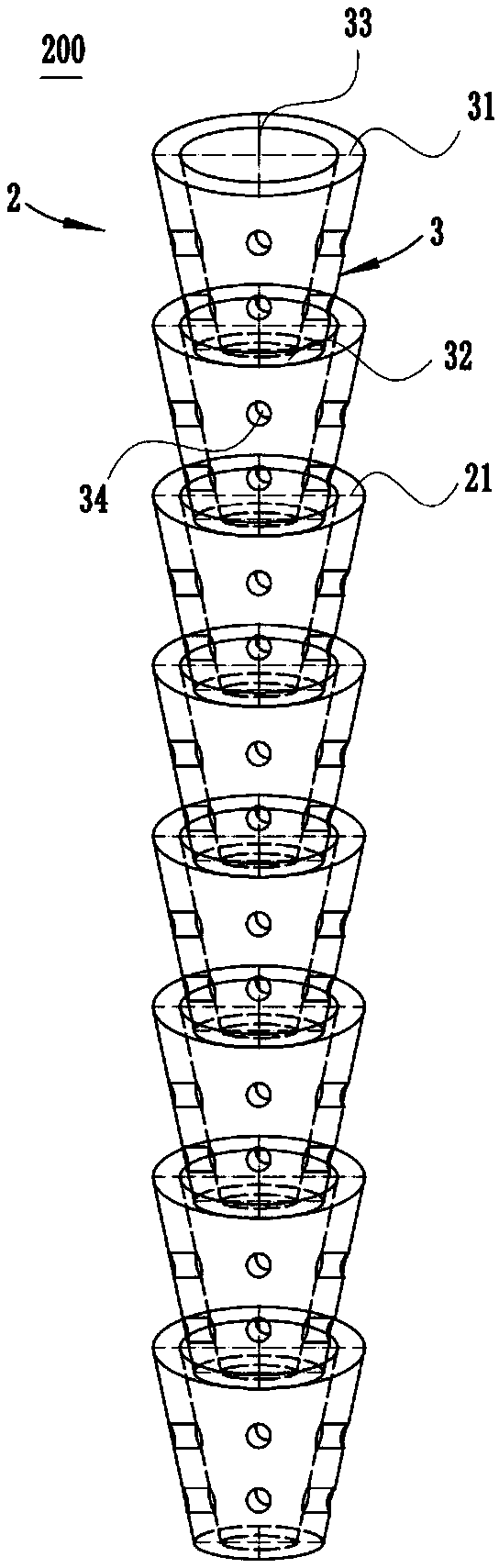
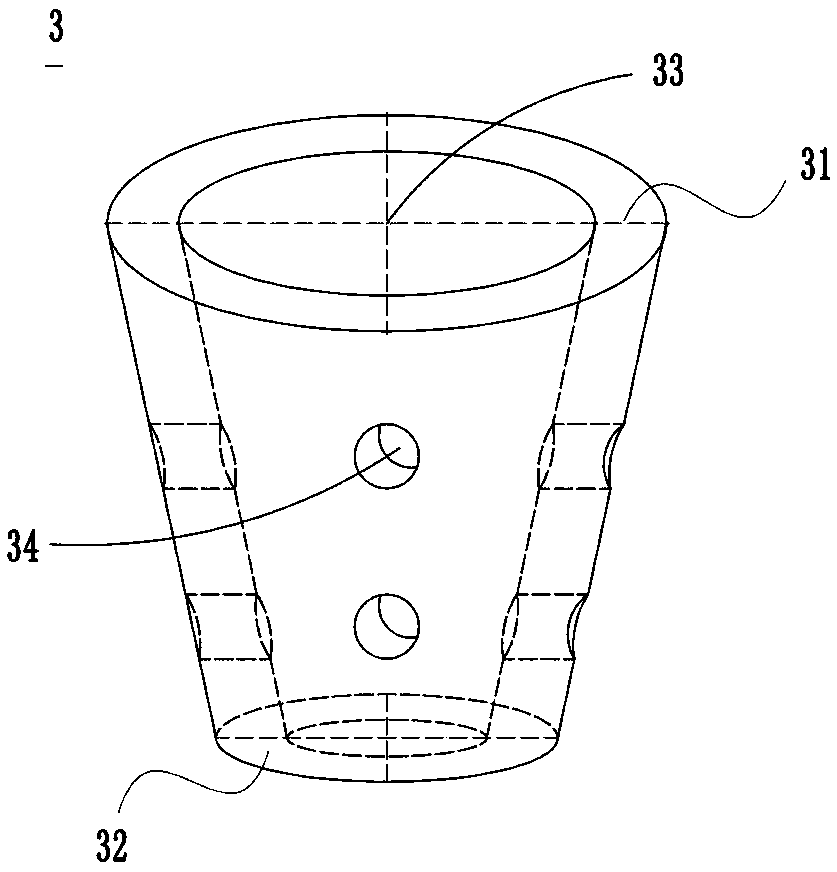
[0035] The second embodiment: according to the attached figure 2 ~ attached Figure 5 As shown, the uplift pile 200 includes a composite pile body 2, which is composed of a plurality of sub-pile bodies 3 nested in each other. Each sub-pile body 3 is an integral part, and each sub-pile body 3 is in the shape of a circular platform. Each sub-pile body 3 has a first open end 31 and a second open end 32 and cement between the first and second open ends. Slurry flow channel 33, the diameter of the first open end 31 is greater than the diameter of the second open end 32, the second open end 32 of one sub-pile body 3 in the adjacent two sub-pile bodies 3 is sleeved on the other sub-pile body 3 Inside the first open end 31, the sleeve joints of the first and second open ends protrude outward to form the occlusal part / hook-shaped part 21 where the uplift pile 200 and the building soil layer interlock, and a plurality of cement slurry flow channels 33 are sequentially connected. In g...


PUM


Abstract

The invention discloses an uplift pile and a construction method thereof, and belongs to the technical field of building construction. The technical problem that in the prior art, the uplift capacityof the uplift pile in the prior art is not high I solved. Two technical schemes are included. In the first and second technical scheme, a structure with one pile body and multiple pile main bodies isprovided, engaging portions / barb portions formed through outward protruding of the connecting positions of the pile main bodies can be used for being engaged with a building soil layer, and the upliftcapacity is improved; in the first technical scheme, a through cement paste runner is arranged, the strength of the whole pile body is improved, according to the second technical scheme, multiple subpile bodies are arranged to form a combined pile body structure, the length of the pile bodies can be achieved by increasing or decreasing the sub pile bodies, acting according to circumstances is achieved, the cement paste runners with the diameters being larger in upper and smaller in lower are arranged in the sub pile bodies, the combined pile body forms a whole body, and the strength of connection between the sub pile bodies can be improved.

Description

technical field [0001] The invention relates to the technical field of building construction, in particular to an uplift-resistant pile and a construction method for the uplift-resistant pile. Background technique [0002] The Chinese invention patent application with the publication number CN102363956A discloses a kind of anti-uplift pile. Aiming at the technical problem that the uplift pile is weak due to the buoyancy of groundwater and the welding between the piles and the strength is not high, it is stated in its specification discloses the following technical scheme; it increases the connection strength between the piles and increases the resistance of the pile to the buoyancy of groundwater by increasing the friction force of the entire pile body facing the underground soil layer, and adopts a solid structure pile, pile The connection with the pile is fastened by fasteners such as connecting plates and bolts, and the overlapping parts between the plates are all welded....

Claims


Application Information

Patent Timeline
Patent Type & Authority Applications(China)
IPC IPC(8): E02D5/48E02D5/50E02D5/52E02D31/12
CPCE02D5/48E02D5/50E02D5/523E02D31/12E02D2200/1692E02D2250/003
Inventor 左熹倪红周桂云顾荣蓉
Owner JINLING INST OF TECH
Why Eureka
Try Eureka