Textile yarn ball drying device capable of rotating obliquely

The invention relates to a drying equipment and a technology of tilting and rotating, which is applied in the field of yarn ball drying equipment for textiles, and can solve the problems of inconvenient drying and small heating area of ​​the yarn ball drying operation, so as to facilitate heat dissipation, improve work efficiency, and achieve better effects. full effect

Active Publication Date: 2018-10-19
XUZHOU ZHENFANG TEXTILE CO LTD
View PDF5 Cites 2 Cited by
  • Summary
  • Abstract
  • Description
  • Claims
  • Application Information

AI Technical Summary

Problems solved by technology

[0006] Aiming at the deficiencies of the prior art, the present invention provides a textile yarn ball drying equipment that can be tilted and rotated, which solves the problem of small heating area and inconvenient drying in the yarn ball drying operation

Method used


Image

  • Textile yarn ball drying device capable of rotating obliquely
  • Textile yarn ball drying device capable of rotating obliquely
  • Textile yarn ball drying device capable of rotating obliquely

Examples


Embodiment 1

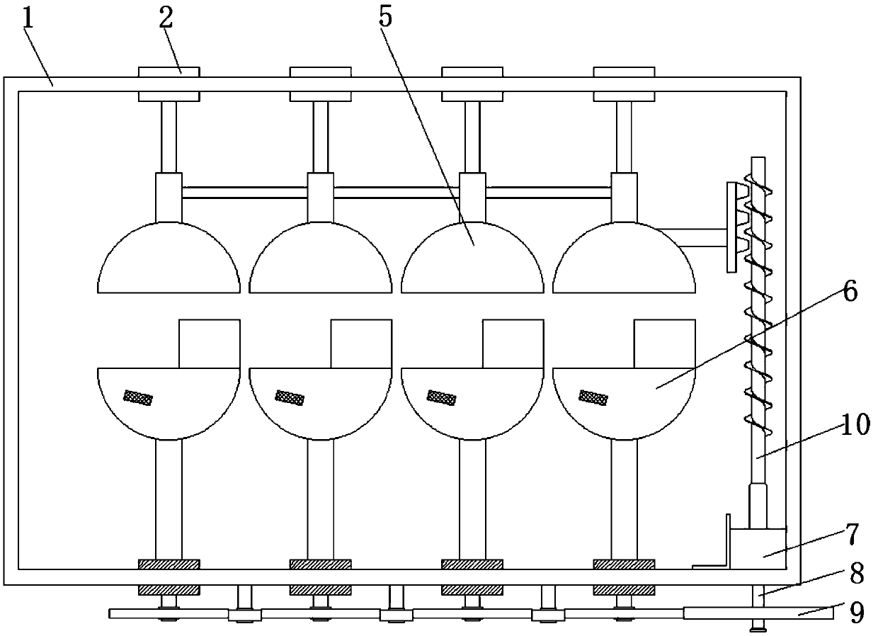
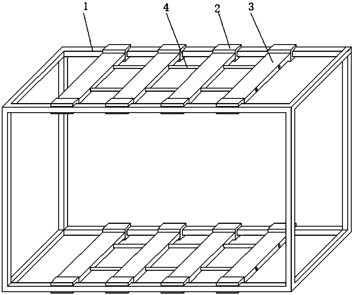
[0041] Such as Figure 1-2 As shown, the present invention provides a technical solution: a tiltable and rotatable textile yarn ball drying equipment, comprising a cube frame 1, two prisms at the top of the frame 1 and two prisms at the bottom of the frame 1 are fixedly connected with 4-8 groups of C-shaped cardboards 2, and between the two C-shaped cardboards 2 at the top and between the two C-shaped cardboards 2 at the bottom are fixedly connected with a placement plate 3, and the adjacent An arc-shaped guide tube 4 is fixedly connected between the two placement plates 3, a centralized drying treatment mechanism 5 is provided at the bottom of the C-shaped pallet 2 located above, and a centralized drying treatment mechanism 5 is arranged at the bottom of the C-shaped pallet 2 located below. Anti-action force rotation mechanism 6, the lower right corner of the square frame 1 is fixedly connected with a bidirectional motor 7 through the L-shaped reinforcing plate, the output en...

Embodiment 2

[0043] Such as Figure 1-4 As shown, a tilting and rotating textile yarn ball drying equipment includes a cube frame 1, and the two prisms on the top of the frame 1 and the two prisms on the bottom of the frame 1 are fixedly connected with 4-8 sets of C-shaped cards. board 2, and between the two C-shaped card boards 2 at the top and the two C-shaped card boards 2 at the bottom are fixedly connected with the placement board 3, and the two adjacent placement boards 3 are fixed It is connected with an arc-shaped guide pipe 4, and the bottom of the upper C-shaped pallet 2 is provided with a centralized drying treatment mechanism 5, and the bottom of the lower C-shaped pallet 2 is fixedly connected with an anti-force rotating mechanism 6. The lower right corner of the frame 1 is fixedly connected to the bidirectional motor 7 through the L-shaped reinforcing plate, the output end of the bottom of the bidirectional motor 7 is fixedly connected to the output end, and the output end is...

Embodiment 3

[0046] Such as Figure 1-7 As shown, a tilting and rotating textile yarn ball drying equipment includes a cube frame 1, and the two prisms on the top of the frame 1 and the two prisms on the bottom of the frame 1 are fixedly connected with 4-8 sets of C-shaped cards. board 2, and between the two C-shaped card boards 2 at the top and the two C-shaped card boards 2 at the bottom are fixedly connected with the placement board 3, and the two adjacent placement boards 3 are fixed It is connected with an arc-shaped guide pipe 4, and the bottom of the upper C-shaped pallet 2 is provided with a centralized drying treatment mechanism 5, and the bottom of the lower C-shaped pallet 2 is fixedly connected with an anti-force rotating mechanism 6. The lower right corner of the frame 1 is fixedly connected to the bidirectional motor 7 through the L-shaped reinforcing plate, the output end of the bottom of the bidirectional motor 7 is fixedly connected to the output end, and the output end is...


PUM


Abstract

The invention relates to the field of textile equipment and discloses a textile yarn ball drying device capable of rotating obliquely. The textile yarn ball drying device comprises a cube frame. Two edge columns on the top of the frame are fixedly connected with 4-8 sets of C-shaped clamping plates, and the two edge columns at the bottom of the frame are fixedly connected with 4-8 sets of C-shapedclamping plates. A carrying plate is fixedly connected between every two corresponding C-shaped clamping plates located above, and a carrying plate is fixedly connected between every two correspondingly C-shaped clamping plate located below. Arc-shaped guide pipes are fixedly connected between the two adjacent carrying plates. A centralized drying treatment mechanism is arranged under each C-shaped clamping plate located above. Through the textile yarn ball drying device, the problems that yarn balls are small in heating area and are inconvenient to dry during drying operation are solved. Through cooperation of the centralized drying treatment mechanisms, acting force resistant rotating mechanisms and a vibration amplitude mechanism, the heating area of the dried surfaces of the yarn balls can be larger, and the yarn balls can be dried more rapidly, and the working efficiency can be effectively improved.

Description

technical field [0001] The invention relates to the technical field of textile equipment, in particular to a tilting and rotating textile yarn ball drying equipment. Background technique [0002] A drying device refers to a combination of a series of mechanical equipment that dries moisture or other liquids on the surface of an object through certain technical means. The current popular drying technologies are mainly ultraviolet drying, infrared drying, electromagnetic drying and hot air drying. They have their own characteristics and are widely used in the drying of various mechanical equipment and food. Yarn balls are yarns wound into balls, which are convenient to carry and store. In the preparation of yarn balls, drying devices are often used. Commonly used textile yarn ball drying equipment has the disadvantage of a small working heating surface, which makes the work efficiency low. [0003] For example, the Chinese patent CN201720452908.5 discloses a yarn ball dryin...

Claims


Application Information

Patent Timeline
Patent Type & Authority Applications(China)
IPC IPC(8): F26B9/06F26B21/10F26B25/00
CPCF26B9/06F26B21/10F26B25/00F26B21/001F24H3/0405
Inventor 孙载位
Owner XUZHOU ZHENFANG TEXTILE CO LTD
Why Eureka
Try Eureka