Drying device for automobile accessories
A technology for drying devices and auto parts, applied in drying, dryers, heating devices, etc., can solve the problems of affecting the quality of finished parts, uneven drying, low drying efficiency, etc., and achieve enhanced drying effect, Good drying effect and improved drying efficiency
Active Publication Date: 2018-10-19
宁波鑫神泽汽车零部件有限公司
View PDF7 Cites 5 Cited by
- Summary
- Abstract
- Description
- Claims
- Application Information
AI Technical Summary
Problems solved by technology
However, during the baking process, when the accessories are placed flat on the conveyor belt, the parts in contact with the conveyor belt are not ventilated, which makes it difficult to dry the parts and the drying is uneven, which not only affects the quality of the finished accessories, but also Dry efficiency is low
Method used
View moreImage
Smart ImageViewing Examples
Examples
Embodiment Construction
[0018] The present invention will be described in further detail below by means of specific embodiments:
Login to View More PUM
 Abstract
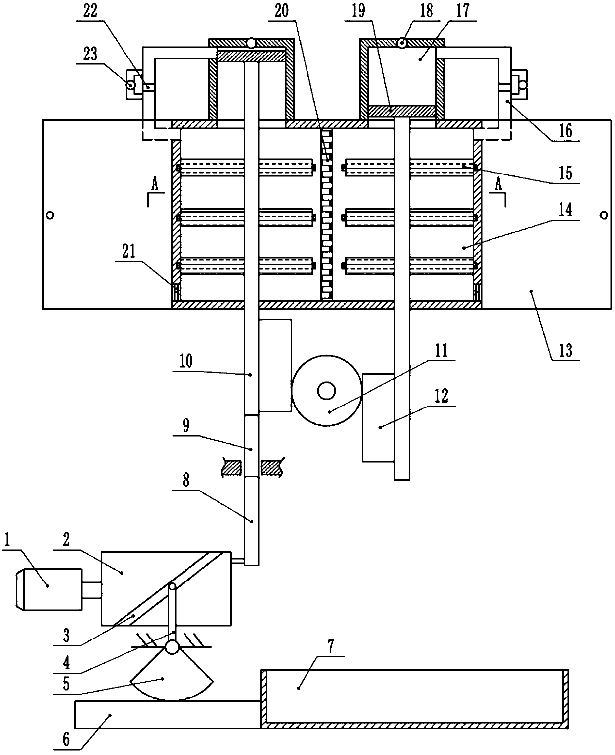
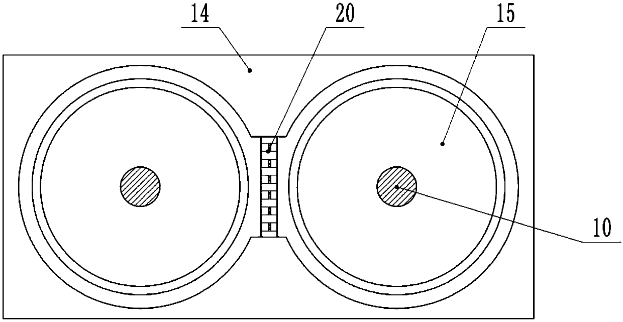
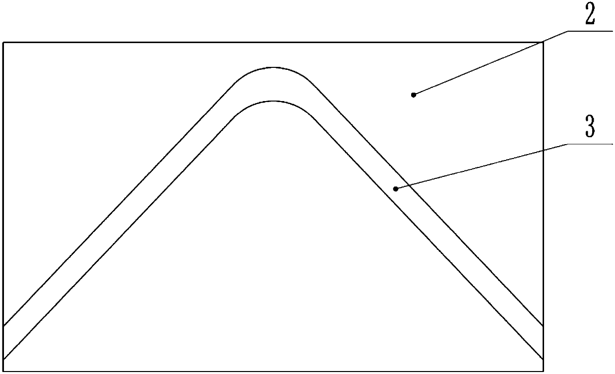
The invention belongs to the technical field of drying equipment, and particularly discloses a drying device for automobile accessories. The drying device comprises a drying box and a motor. An outputshaft of the motor is connected with a rotating drum. A connecting rod is hinged to the end face of the rotating drum. A sliding rod is hinged to the end of the connecting rod. The sliding rod is slidably connected to a frame. The drying box is located above the rotating drum and is internally provided with a heating plate and multiple rotating screens. Two cylinder barrels are arranged on the drying box. A piston is arranged in each cylinder barrel, a moving rod is arranged on each piston, and racks are correspondingly arranged on the two moving rods. Gears are rotationally connected to theframe. The part, inside the drying box, of each moving rod is a screw rod, and the moving rods are fixedly connected with the sliding rod. The upper part of each cylinder barrel communicates with an inner cavity, and a one-way valve is arranged on the top wall of each cylinder barrel. A cooling screen is slidably connected to the frame, a first rack is arranged on the cooling screen, a sector gearis rotationally connected to the frame, a swinging rod is arranged on the sector gear, a chute is formed in the side wall of the rotating drum, and the swinging rod is slidably arranged in the chute.By the adoption of the scheme, the drying effect is good, and the drying efficiency is high.
Description
technical field [0001] The invention belongs to the technical field of drying equipment, in particular to a drying device for auto parts. Background technique [0002] At present, with the development of science and technology, the field of mechanical processing is also making rapid progress. After the machining of mechanical parts is completed, it is often necessary to further process the precision of the mechanical parts, remove the burrs on the surface and clean them again. When the cleaning is completed Finally, it is necessary to remove the moisture contained on the surface of the fittings in time, so as to achieve the purpose of drying the fittings, which can effectively avoid the corrosion of the fittings. The existing technology usually uses a drying device to dry the metal fittings, but the existing Due to problems such as unreasonable structural design, the drying device cannot effectively remove the moisture contained on the surface of the fittings during drying, ...
Claims
Login to View More Application Information
Patent Timeline
 Patent Type & Authority Applications(China)
IPC IPC(8): F26B9/08F26B21/00F26B23/00F26B25/04F26B25/00
CPCF26B9/085F26B21/004F26B23/00F26B25/00F26B25/04
Inventor 王健
Owner 宁波鑫神泽汽车零部件有限公司
Features
- R&D
- Intellectual Property
- Life Sciences
- Materials
- Tech Scout
- Unparalleled Data Quality
- Higher Quality Content
- 60% Fewer Hallucinations
Learn More Browse by: Latest US Patents, China's latest patents, Technical Efficacy Thesaurus, Application Domain, Technology Topic, Popular Technical Reports.
© 2025 PatSnap. All rights reserved.Legal|Privacy policy|Modern Slavery Act Transparency Statement|Sitemap|About US| Contact US: help@patsnap.com


