
A High Speed ​​Transient Schlieren System

A schlieren and transient technology, applied in the field of aerospace experiments, can solve the problems of flow display accuracy drop, discharge instability, and confidence drop, and achieve the effect of solving image acquisition problems and increasing sampling frequency

Active Publication Date: 2020-06-09
CHINA ACAD OF AEROSPACE AERODYNAMICS
View PDF8 Cites 0 Cited by
  • Summary
  • Abstract
  • Description
  • Claims
  • Application Information

AI Technical Summary

Problems solved by technology

Recently (2013) the combination of pulsed spark light source and high-speed camera appeared at home and abroad. Although its pulse bandwidth can reach 25ns, it solves the problem of time-average effect in flow field testing, but it is easy to drift due to pulse sparks and air ionospheric accumulation. The discharge is unstable, which reduces the accuracy and confidence of the flow display

Method used


Image

  • A High Speed ​​Transient Schlieren System
  • A High Speed ​​Transient Schlieren System
  • A High Speed ​​Transient Schlieren System

Examples


Embodiment Construction

[0033] The present invention will be described in detail below in conjunction with the accompanying drawings and examples.

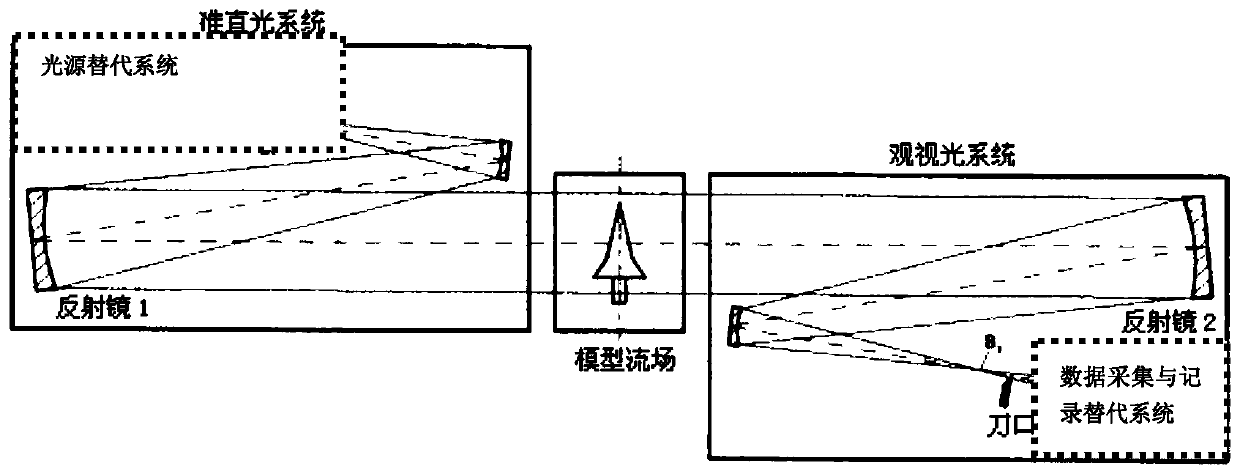
[0034] The light source and light source image of the traditional double-mirror parallel light schlieren instrument are respectively located on both sides of the schlieren system. The light source is usually a tungsten halogen lamp or the current LED light source. After converging, it passes through a slit and a horseshoe mirror to form parallel light, and then focuses on the knife edge after passing through the flow field. After being cut by the knife edge, it enters the image acquisition and processing system to complete the measurement of the density gradient field.

[0035] The main performance indicators of conventional schlieren instruments are sensitivity and sharpness.

[0036] The sensitivity of the schlieren instrument can be reflected by the minimum deflection angle ε m i n express,

[0037]

[0038] In the formula, a is the slit width ...


PUM


Abstract

Disclosed is a high speed transient schlieren system. The high speed transient schlieren system includes an alignment light system consisting of a light source substitution system, a horseshoe mirrorI and a reflecting mirror I, a viewing light system consisting of a horseshoe mirror II, a reflecting mirror II, a knife edge and a data collection and record substitution system, and a synchronous control system. The alignment light system and the viewing light system are arranged in a Z-symmetry off the axis. When a flow field of a wind tunnel test is established, the synchronous control systememits a control signal to control the light source substitution system and the data collection and record substitution system to work. The light source substitution system converts high frequency pulse laser into high frequency pulse parallel light through the horseshoe mirror I and the reflecting mirror I after space alignment and astigmatic difference elimination. The pulse parallel light passesthrough the flow field of a test section model of a wind tunnel, and then converges to the knife edge through the reflecting mirror II and the horseshoe mirror II. The data collection and record substitution system collects transient density gradient change images after the cutting by the knife edge. The high frequency is frequency corresponding to the moving speed of a quasi-sequential structureof the flow field of the test section model. A pulse bandwidth meets the requirements of the Taylor flow field freezing hypothesis.

Description

technical field [0001] The invention relates to a plurality of key components for establishing high-speed transient schlieren technology. The schlieren instrument formed by these devices can be used as a high-frequency test technology for realizing the density gradient space flow field under the Taylor freezing assumption, and belongs to the field of aerospace experiment technology. Background technique [0002] At present, the technical problem faced by aerospace wind tunnel experiment measurement is the simultaneous measurement and display of complex space flow field characteristics (such as transition, shock wave / shock wave interference, shock wave / boundary layer interference, etc.). The traditional schlieren technique (proposed by Teppler in 1864 and applied 22 years later) uses a continuously emitting tungsten-halogen lamp as the light source, and the collected images are recorded on film. Due to the time-average effect brought by the continuous light source, the wave s...

Claims


Application Information

Patent Timeline
Patent Type & Authority Patents(China)
IPC IPC(8): G01M9/06
CPCG01M9/067
Inventor 甘才俊石伟龙康国剑王克李烺
Owner CHINA ACAD OF AEROSPACE AERODYNAMICS
Learn More