Falling tension fatigue test device for power construction safety belt

A tensile fatigue and electrical construction technology, which is applied in the application of repetitive force/pulse force to test the strength of materials, measuring devices, instruments, etc., can solve the problem that the impact debris of the counterweight is easy to splash and hurt people, the test interval is long, and the efficiency Low-level problems, to achieve the effect of shortening the test interval time and solving inefficiency

Active Publication Date: 2018-10-19
KUNMING FEIXIANG MATERIAL TECH CO LTD
View PDF8 Cites 2 Cited by
  • Summary
  • Abstract
  • Description
  • Claims
  • Application Information

AI Technical Summary

Problems solved by technology

[0007] In order to solve the above technical problems, the present invention provides a drop tension fatigue test device for safety belts in electric power construction, to solve the problem that the existing safety belt test device has a long test interval, low efficiency of continuous impact test, and the problem of counterweight The problem that the impact debris is easy to splash and hurt people

Method used


Image

  • Falling tension fatigue test device for power construction safety belt
  • Falling tension fatigue test device for power construction safety belt
  • Falling tension fatigue test device for power construction safety belt

Examples


Embodiment

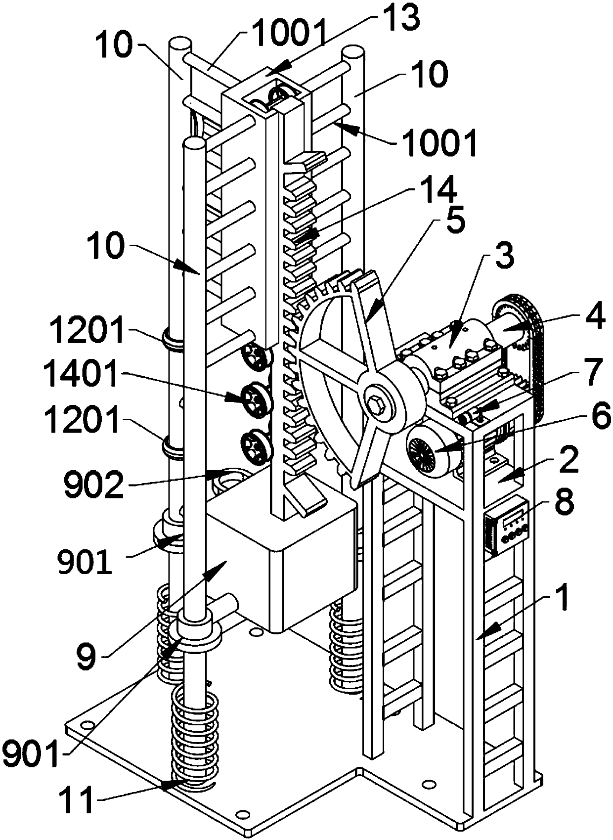
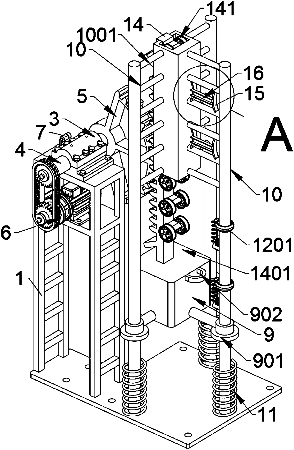
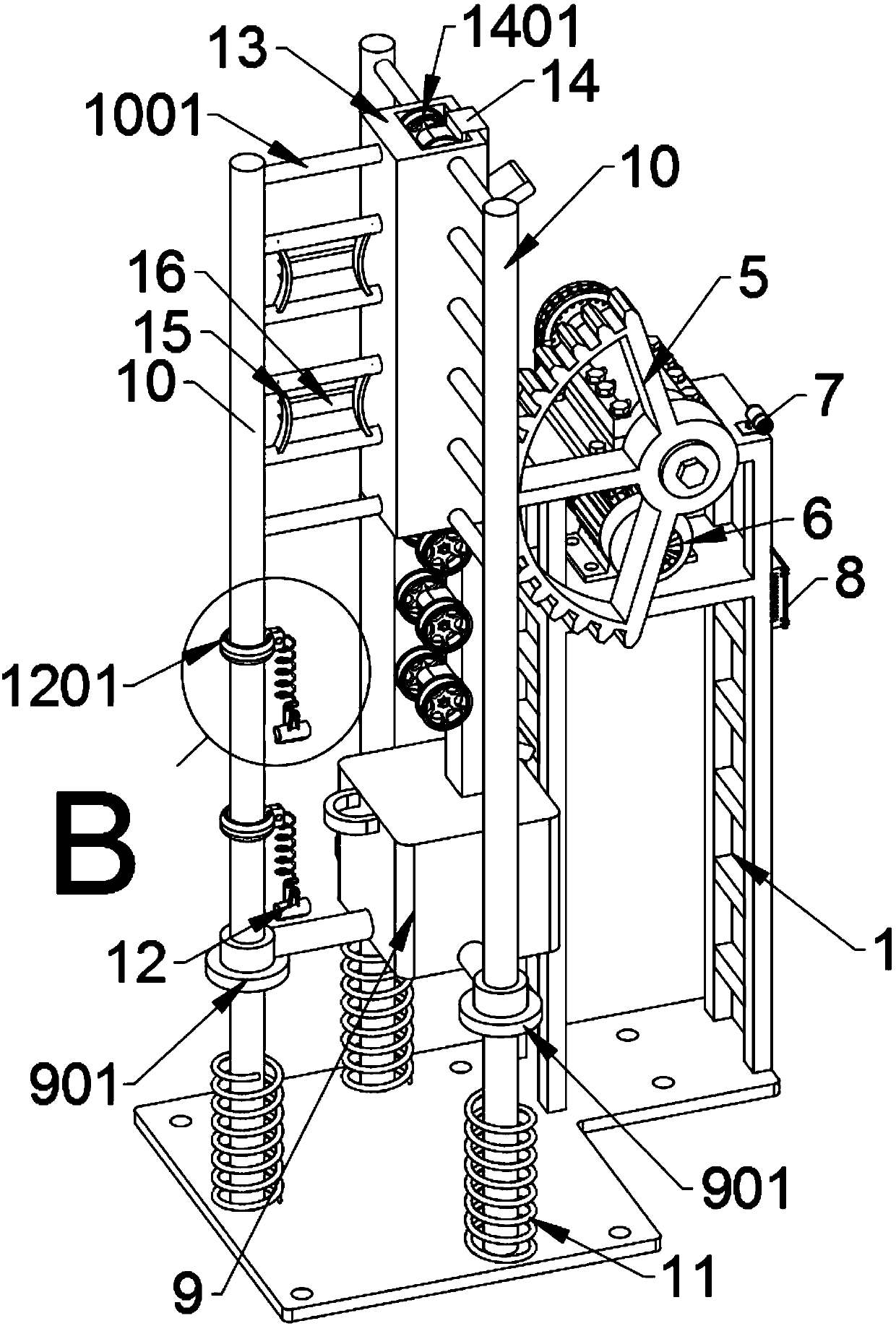
[0033] as attached figure 1 to attach Figure 8 Shown:

[0034]The invention provides a drop tension fatigue test device for safety belts in electric power construction, which includes a supporting mounting frame 1, a motor mounting plate 2, a bearing seat 3, a rotating shaft 4, a sector gear 5, a driving motor 6, a photoelectric sensor switch 7, and a control Electric box 8, lead block 9, positioning ring 901, hanging ring 902, support shaft 10, welding strut 1001, buffer spring 11, clip 12, slip ring 1201, pin 1202, track groove 13, sliding hanging plate 14, roller 1401, the arc-shaped support plate 15 and the leaning groove 16, the support installation frame 1 is welded and supported on the rear side of the base plate protruding from the rectangular plate, and the top of the support installation frame 1 is screwed and fixed with a bearing seat 3; A motor mounting plate 2 is supported and welded between the supporting mounting frames 1, and the motor mounting plate 2 is lo...


PUM

PropertyMeasurementUnit
diameteraaaaaaaaaa

Abstract

The invention provides a falling tension fatigue test device for a power construction safety belt. The falling tension fatigue test device comprises slip rings, contact pins, track grooves, a slidinghanger plate, rollers, arc-shaped supporting plates and reclining grooves; the rear end of the rail groove is provided with an opening; two jacking plates are symmetrically supported at the exterior eaves of the rear ends of the left side wall and the right side wall of the rail groove; the length of the rail groove is half of the length of the sliding lifting plate; a rotary shaft penetrates through a bearing block in an inserted mode; the left end of the rotary shaft is sleeved with a sector gear with the diameter of 0.5 m in a locked mode; the right end of the rotary shaft is sleeved with agear in a locked mode; the gear is in transmission with a gear of a driving motor through a chain; and a photoelectric sensing switch is arranged on the surface, on one side of the bearing block, ofa mounting plate in a locked and supported mode through screws. According to the falling tension fatigue test device, the two sets of arc-shaped supporting plates are arranged, the two sets of arc-shaped supporting plates and the two reclining grooves in the two sets of arc-shaped supporting plates can be supported and combined to form two reclining frames, and the two reclining frames can simulate chest and abdomen skeletons of human bodies, so that the safety belt can be conveniently reclined and locked on the reclining frames.

Description

technical field [0001] The invention belongs to the technical fields of safety belt test device and electric equipment, and more specifically relates to a drop tension fatigue test device for safety belts in electric power construction. Background technique [0002] Seat belts are widely used in construction, electrical engineering, vehicles, high-altitude activities and other fields, and are important accessories to ensure personal safety. Therefore, the load-bearing capacity of seat belts is very important, and safety belts need to be tested for drop impact fatigue before leaving the factory. [0003] After searching, for example, the patent No. CN201620267354.7 discloses a safety belt buffer test device, which includes a test frame, a buffer to be tested connected with an iron man, a lifting device, a detection device, and a console; the lifting device includes Two chutes that are vertically arranged on both sides of the test frame and protrude from the upper end of the t...

Claims


Application Information

Patent Timeline
Patent Type & Authority Applications(China)
IPC IPC(8): G01N3/32
CPCG01N3/32G01N2203/0005G01N2203/0033G01N2203/0073G01N2203/0282
Inventor 不公告发明人
Owner KUNMING FEIXIANG MATERIAL TECH CO LTD
Why Eureka
Try Eureka