A device for testing the response speed of a sensor and its testing method

A technology of response speed and test method, which is applied in the measurement device, the structural details of gas analyzers, instruments, etc., can solve the problem of difficult to obtain millisecond or microsecond response speed, inability to accurately characterize the real performance of the device, and inability of the test system. General and other issues, to achieve the effect of novel testing methods, improved scope of use, and clear principles

Active Publication Date: 2021-06-08
SOUTHEAST UNIV
View PDF6 Cites 0 Cited by
  • Summary
  • Abstract
  • Description
  • Claims
  • Application Information

AI Technical Summary

Problems solved by technology

These systems generally have a slow response of the system itself, which cannot accurately characterize the real performance of the device; the system is complex in structure, inconvenient to use, and difficult to maintain; the performance is unstable; the test system cannot be used universally; Better cavity fast response and other disadvantages
For example, moving the sample quickly or using a fast gas valve will introduce mechanical and electromagnetic disturbances, which will be detrimental to the test results
It is also difficult for its own testing mechanism or organization to obtain a response speed of milliseconds or microseconds

Method used


Image

  • A device for testing the response speed of a sensor and its testing method
  • A device for testing the response speed of a sensor and its testing method

Examples


Embodiment 1

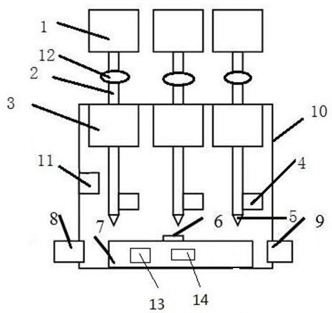
[0023] Such as figure 1 As shown, a device for testing the response speed of a sensor includes three sets of air intake mechanisms, a test cavity, an air intake channel, and an exhaust mechanism. The air intake channels and exhaust mechanisms are respectively located on both sides of the test cavity. A reference sensor is provided in the test chamber, a sample holder is provided at the bottom, a temperature regulator, a position regulator and a sensor to be tested are provided on the sample holder; an air inlet extending into the test chamber is provided above the sample holder mechanism, the air intake structure includes an air supply tank, an air guide tube, a valve 2, an air guide tube azimuth adjustment mechanism, a valve 1 and a nozzle, and the air supply tank communicates with the valve 2, valve 1 and nozzle in sequence through the air guide tube The airway azimuth adjustment structure, valve 1 and nozzle are all in the test chamber, and the airway azimuth adjustment mec...

Embodiment 2

[0025] A test method for a device for testing the response speed of a sensor includes the following steps: Step 1, using software to simulate the size of the nozzle, the relative position of the nozzle and the sensor to be tested, and the switching speed of the valve 1, that is, analyze the pressure at the nozzle according to the fluid mechanics method Uniformity, so as to determine the size of the nozzle, the relative position of the nozzle and the sensor to be tested, and the switching speed of valve 1; step 2, connect all test signals; prepare to test the target gas and background gas, according to the analysis, select a nozzle with a suitable size and shape, and the size of the nozzle should be It is larger than the size of the sensitive surface of the sensor to be tested to ensure that the ejected gas can cover the entire sensing surface area; step 3, the background gas is introduced into the test cavity from the air inlet channel until the background gas is distributed sta...


PUM


Abstract

The invention discloses a device for testing the response speed of a sensor and a testing method thereof. The device includes at least one set of test chambers, an air intake mechanism and an exhaust mechanism. The test chamber is provided with a reference sensor and a sample holder, the position and temperature of the sample holder can be adjusted, and an air intake mechanism is arranged above the sample holder, which communicates with the valve 2, the valve 1 and the nozzle in sequence through the air supply tank , the airway azimuth adjustment mechanism is located on the airway between the valve 2 and the valve 1, and is located in the test cavity. Before the test, use the software simulation device to determine the position of the components and the opening of each valve; determine all the test signals of each important connection; pass the background gas into the test cavity from the air inlet channel, and read the test value of the sensor device; adjust the sensor to be tested Inject the test target gas into the relative position of the nozzle to test the transient response of the sensor to be tested. The device of the invention has simple structure, novel method, high efficiency and is not restricted by the use environment.

Description

technical field [0001] The invention belongs to the technical field of advanced sensitive device testing, and in particular relates to a device for testing the response speed of a sensor and a testing method thereof. Background technique [0002] Sensors are widely used in daily life, high-tech applications and other fields and play an important role. One of the factors affecting the performance of the sensor depends on the response speed of the sensor, so the fast response of the sensor device is very important. Conventional gas sensing devices usually have a response speed of "second" level. It is suitable for some applications. For example, the detection of harmful gases in daily life does not require a very fast detection speed. However, it is not suitable for high-speed, large dynamic range, and fast response occasions, especially for millisecond or microsecond-level response occasions. At this time, it is necessary to develop sensor devices with fast response for s...

Claims


Application Information

Patent Timeline
Patent Type & Authority Patents(China)
IPC IPC(8): G01N33/00
CPCG01N33/007G01N2033/0072
Inventor 万能赵小康徐康邵志勇
Owner SOUTHEAST UNIV
Why Eureka
Try Eureka