Fiber grating accelerometer in optical fiber

An accelerometer and fiber grating technology, which is applied in the direction of acceleration measurement using inertial force, and can solve problems such as low processing accuracy

Inactive Publication Date: 2018-10-19
BENGBU COLLEGE
View PDF6 Cites 2 Cited by
  • Summary
  • Abstract
  • Description
  • Claims
  • Application Information

AI Technical Summary

Problems solved by technology

However, at this stage, the processing accuracy of these methods is low

Method used


Image

  • Fiber grating accelerometer in optical fiber

Examples


Embodiment Construction

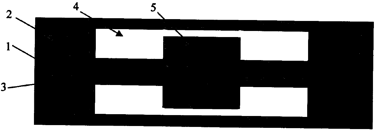
[0013] For example, as attached figure 1 As shown, for an ordinary optical fiber (core diameter is 9 microns, cladding outer diameter is 125 microns), a femtosecond laser point-by-point writing method can be used to write a 50 micron long grating (G.D.Marshall, et al., "Point- by-pointwritten fiber-Bragg gratings and their application in complex grating designs, "Optics Express, vol. 18, pp. 19844-19859, 2010). Then use femtosecond laser etching method and oil immersion method to write 3D pattern on this optical fiber. The grating can be machined down to 11 microns in diameter. The diameter of the retained fiber cladding can be positioned 100 microns; a 5 micron wide ring can be cut around it. On the other side of the retained fiber cladding, it can be cut into the same size structure as the grating side. When the retained fiber cladding is accelerated, the grating will measure this acceleration as a change in its resonant wavelength. In order to better protect its structu...


PUM


Abstract

The invention relates to a fiber grating accelerometer in an optical fiber. According to the principle of an accelerometer, the only method to simultaneously increase the sensitivity and eigenfrequency of the accelerometer is to reduce the length of the vibrating arms of the accelerometer. According to the fiber grating accelerometer in the optical fiber, a femtosecond laser micro-machining technology is adopted to cut the cladding of the optical fiber, so that the diameter of the optical fiber at the vibration portion of the accelerometer can be decreased, and therefore, vibration arms can beformed at a fiber grating, and an inertial component can be formed in the optical fiber. As shown in the drawings described in the descriptions of the invention, most of the cladding of the grating is removed, so that the cladding can form the vibrating arms. Although the mass of the inertial component (fiber cladding block) between the two vibrating arms which are formed by means of laser cutting is small, the diameter of the vibrating arms is smaller, and as a result, stress generated by vibration is still concentrated on the vibrating arms, and therefore, the length of the fiber grating and the return wavelengths of the fiber grating can be changed, and vibration information can be obtained. The diameter ratio of the inertial component and the vibrating arms can be changed, so that thesensitivity and eigenfrequency of the fiber grating accelerometer can be changed.

Description

1. Technical field: [0001] The present invention relates to fiber grating accelerometers. 2. Technical Background [0002] Optical fiber is composed of core, cladding and coating. The core is at the very center and is typically 9 microns in diameter. The cladding surrounds the core; together they are typically 125 microns in diameter. By irradiating the fiber with laser light, the refractive index of the fiber core can be periodically changed to form a grating. Optical fibers containing gratings are often referred to as fiber gratings. When the strain of the fiber grating changes, its resonant wavelength will change accordingly. Under the condition that the temperature is basically constant, the strain change can be obtained by measuring its resonance wavelength. [0003] Fiber Bragg Grating acceleration sensors are usually made by connecting a small mass (inertial element) and fiber Bragg grating together; then, they are packaged and protected. Its basic working princ...

Claims


Application Information

Patent Timeline
IPC IPC(8): G01P15/03
CPCG01P15/03
Inventor 李阔
Owner BENGBU COLLEGE
Why Eureka
Try Eureka