Quickly connectable conductive stud structure

A quick connection and stud technology, which is applied in the direction of connection and connection device components, circuits, etc., can solve the problems of appearance traces, deformation, and reduced appearance

Pending Publication Date: 2018-10-19
CHANGZHOU BORI ELECTRIC POWER AUTOMATION EQUIP
View PDF11 Cites 1 Cited by
  • Summary
  • Abstract
  • Description
  • Claims
  • Application Information

AI Technical Summary

Problems solved by technology

[0002] At present, studs in the sheet metal product industry are mainly connected to thin plates by traditional methods such as cold work riveting and welding. However, these methods have defects such as deformation, pre-drilling, and appearance marks. For products with high appearance requirements, Spot welding and riveting marks become factors that reduce aesthetics

Method used


Image

  • Quickly connectable conductive stud structure
  • Quickly connectable conductive stud structure

Examples


Embodiment 1

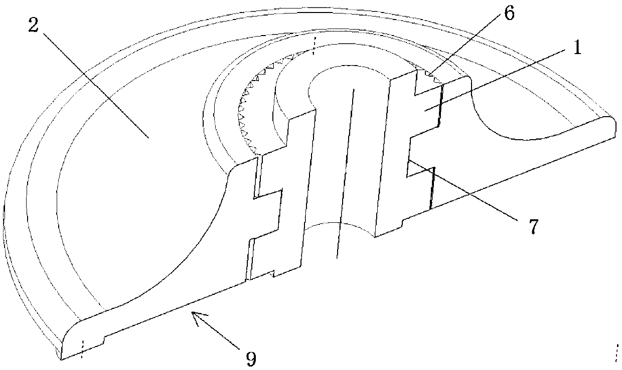
[0023] Such as figure 1 As shown, a quick-connect conductive stud structure includes a sheet metal part 4, a UV adhesive layer 3, a transparent base 2, a metal insert 1 and a stud 5.

[0024] The sheet metal part 4 may be a processing-free sheet such as SGCC, SECC, 304, etc.

[0025] The UV glue layer 3 is specifically formed by curing Dymax (4-20418) UV glue through ultraviolet (UV) irradiation, and other types of UV glue can also be used. As long as the UV glue can be cured to bond the sheet metal part 4 and the transparent base 2 together after being irradiated by ultraviolet rays, the requirement is met. This embodiment only takes Dymax (4-20418) UV glue as an example.

[0026] The transparent base 2 adhered to the sheet metal part 4 by the UV adhesive layer 3, the purpose of setting the transparent base 2 is that it can transmit ultraviolet (UV), use ultraviolet (UV) to pass through the transparent base 2 and then irradiate the coated Dymax (4-20418) UV glue, curing the UV glu...

Embodiment 2

[0034] On the basis of Embodiment 1, a receiving groove is added at the bottom of the transparent base 2. The bottom of the transparent base 2 mentioned here refers to the end where the transparent base 2 and the sheet metal part 4 are connected. The bottom of the transparent base 2 is provided with a accommodating groove 9 for accommodating UV glue, and a leg 8, and the leg 8 is located in the accommodating groove 9, and the leg 8 is supported on the sheet metal 4 and filled in the accommodating The UV glue layer 3 in the groove 9 is connected to the sheet metal part 4. The accommodating groove 9 is provided so that the UV adhesive layer 3 only exists in the accommodating groove 9, and the thickness of the UV adhesive layer 3 and the amount of UV adhesive can be accurately controlled, thereby controlling the height of the entire conductive stud structure. When the top of the stud 5 is connected to the PCB board, the height of the stud 5 is required. Adopting the conductive s...


PUM


Abstract

The invention discloses a quickly connectable conductive stud structure, comprising a sheet metal part, a UV glue layer, a transparent base bonded to the sheet metal part via the UV glue layer, a metal insert embedded in the transparent base by injection molding and provided with an internal threaded hole, and a stud mounted in the internal threaded hole of the metal insert. The metal insert extends out of the bottom end surface of the transparent base to contact the sheet metal part to electrically connect the stud with the sheet metal part. The electrical connection between the stud and thesheet metal part is realized by the connection between the metal insert and the sheet metal part. The transparent base is provided and bonded to the sheet metal part by the UV glue so as to avoid damage to the surface of sheet metal part caused by riveting and welding. The UV glue can quickly connect the transparent base with the sheet metal part and is easy to operate.

Description

Technical field [0001] The invention relates to a quick-connect conductive stud for conductive connection with sheet metal products or metal shells. Background technique [0002] At present, the studs in the sheet metal product industry mainly use traditional methods such as cold work process riveting and welding to connect with thin plates. However, these methods have defects such as deformation, pre-opening, and appearance marks. For products with high appearance requirements, Spot welding and pressure riveting marks have become factors that reduce aesthetics. [0003] The control and protection chassis in the power industry has high requirements for the overall electromagnetic shielding performance. The steel shell has high shielding performance, and the application becomes more widely used. The board is fixed to the shell by studs, so the stud requirements will not affect the appearance quality. It also requires good connection energization performance. [0004] Nowadays, envir...

Claims


Application Information

Patent Timeline
Patent Type & Authority Applications(China)
IPC IPC(8): H01R13/40H01R13/627
CPCH01R13/40H01R13/627
Inventor 邓礼兵李亮陆凯雷孟燕菲柏广枭
Owner CHANGZHOU BORI ELECTRIC POWER AUTOMATION EQUIP
Why Eureka
Try Eureka