Hybrid DC converter valve group online deblocking circuit, method and device

A hybrid DC and inverter technology, applied in the output power conversion device, the conversion of AC power input to AC power output, and the conversion of AC power input to DC power output, etc., can solve the commutation failure, voltage and current harmonics. High content, affecting the stable operation of the power of the DC transmission system, etc., to achieve the effect of smooth input and guaranteed power

Active Publication Date: 2018-10-19
NR ELECTRIC CO LTD +1
View PDF4 Cites 15 Cited by
  • Summary
  • Abstract
  • Description
  • Claims
  • Application Information

AI Technical Summary

Problems solved by technology

[0002] The advantage of current source HVDC transmission based on thyristors is that the loss of the converter is small, and the DC system can be restarted by shifting the phase when a DC line fault occurs; the disadvantage is that the converter on the inverter side works in active inverter and cannot be connected to wireless source system; the inverter side is connected to the weak AC system, and commutation failure is prone to occur after disturbance; the reactive power consumption is large, and the harmonic content of voltage and current is high, so it is necessary to install a filter device to provide reactive power and filter
The advantages of DC transmission based on voltage source converters are high controllability, can be connected to passive systems, and do not require reactive power compensation devices; the disadvantage is that the switching losses of the converters are large, and modular multi-level converters with a half-bridge structure are adopted. The current breaker cannot control the fault current when the DC side is faulty, and the fault can only be removed by disconnecting the AC side circuit breaker after the fault occurs
[0003] For DC side faults, ABB uses a DC circuit breaker with a DC line to solve the DC side fault, but the cost of the DC circuit breaker is high and the reliability has yet to be verified; Siemens use

Method used


Image

  • Hybrid DC converter valve group online deblocking circuit, method and device
  • Hybrid DC converter valve group online deblocking circuit, method and device
  • Hybrid DC converter valve group online deblocking circuit, method and device

Examples


Embodiment 1

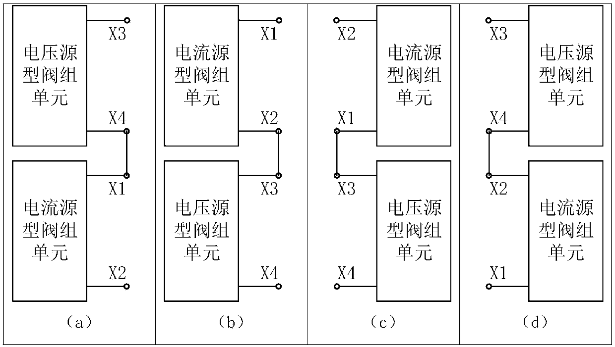
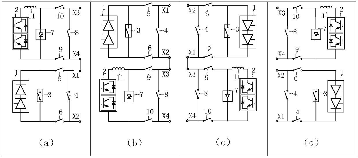
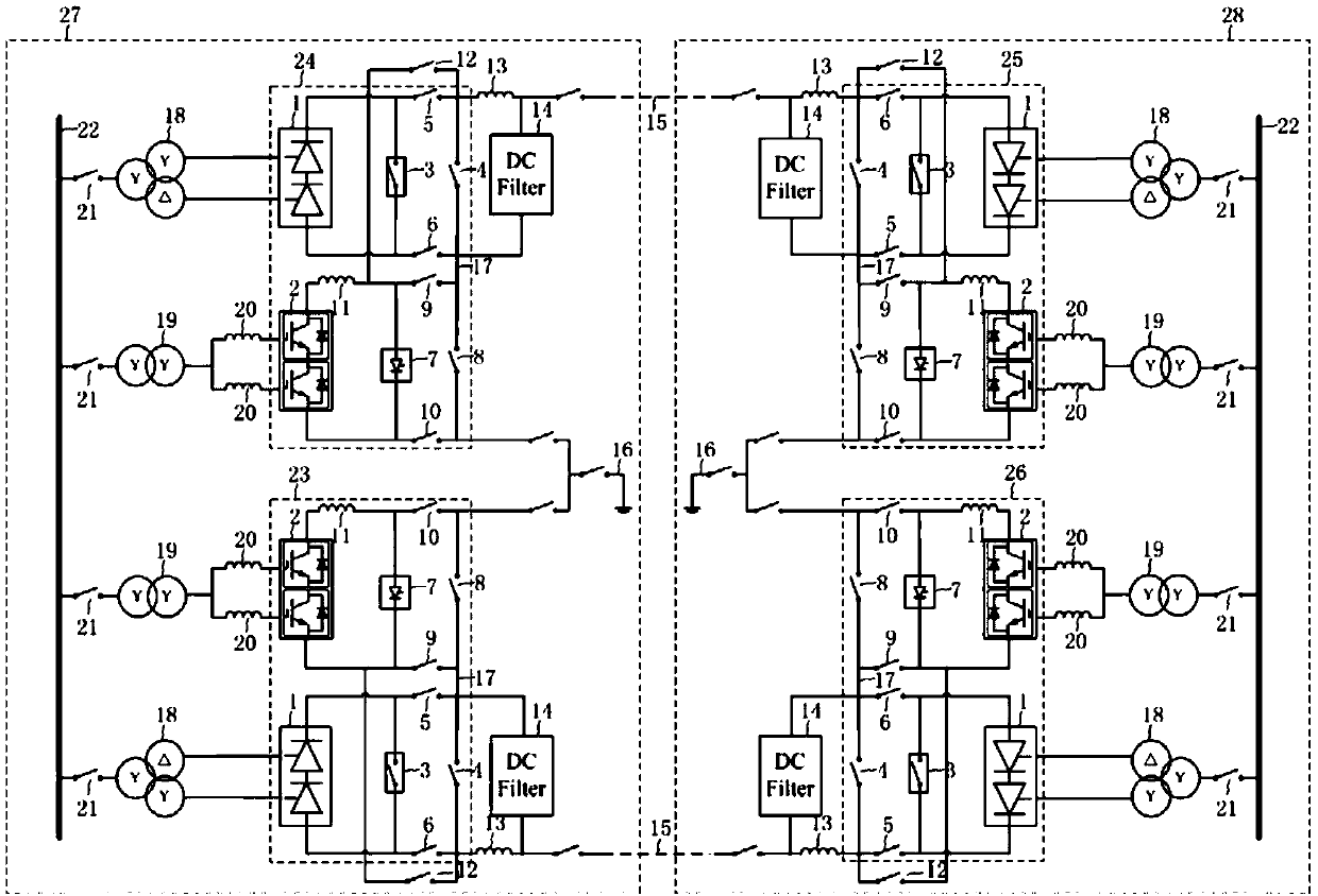
[0041] image 3 It shows that the HVDC power transmission device is all composed of figure 2 The four topological structures shown are an embodiment in which the low-end valve group is composed of a voltage source converter, which connects the rectifier station 27 and the inverter station 28 through the DC line 15 . rectifier station 27 by figure 2 The topological structures (1)23 and (2)24 constitute their negative converters and positive converters respectively, and the inverter station 28 consists of topological structures (3)25 and (4)26 respectively to form their positive converters and negative inverter. Valve group 1 is a grid commutation converter, which is connected to the secondary winding of the thyristor-based current source high-voltage direct current transmission transformer 18, and valve group 2 is a voltage source converter, which is connected to the high-voltage direct current transmission transformer based on the voltage source converter. The secondary w...

Embodiment 2

[0046] Figure 4 It shows that the HVDC power transmission device is all composed of figure 2 The shown four topological structures constitute an embodiment in which the high-end valve group is composed of a voltage source converter, which connects the rectifier station 27 and the inverter station 28 through the DC line 15 . rectifier station 27 by figure 2 The topological structures (1) 23 and (2) 24 constitute the positive converter and the negative converter respectively, and the inverter station 28 consists of the topological structures (3) 25 and (4) 26 to form the negative converter and positive inverter. Valve group 1 is a grid commutation converter, which is connected to the secondary winding of the thyristor-based current source high-voltage direct current transmission transformer 18, and valve group 2 is a voltage source converter, which is connected to the high-voltage direct current transmission transformer based on the voltage source converter. The secondary ...

Embodiment 3

[0051] Figure 5 It shows that the HVDC power transmission device consists of a traditional current source valve group converter and figure 2 An example of two topologies is shown. The rectifier station 27 of the high-voltage direct current transmission device is composed of a topology 30 in which current source valve group units are connected in series, and the inverter station 28 is composed of topological structures (3) 25 and (4) 26 to form its positive converter and negative converter respectively. Valve group 1 is a grid commutation converter, which is connected to the secondary winding of the thyristor-based current source high-voltage direct current transmission transformer 18, and valve group 2 is a voltage source converter, which is connected to the high-voltage direct current transmission transformer based on the voltage source converter. The secondary windings of the transmission transformer 19 are connected. The rectifier station 27 is configured with an AC fil...


PUM


Abstract

The invention discloses a hybrid DC converter valve group online deblocking circuit which is used for the online deblocking of a voltage source converter. The circuit at least comprises a valve groupconnection line connection switch or knife switch of a voltage source type valve group unit, a DC link connection switch or knife switch of the voltage source type valve group unit and a bypass switchor knife switch of a current source type valve unit, or at least comprises a valve group connection line connection switch or knife switch of the voltage source type valve group unit, a neutral busbar connection switch or knife switch of the voltage source type valve group unit, a bypass switch or knife switch of the voltage source type valve unit and a bypass switch or knife switch of the current source type valve unit. The invention also discloses a hybrid DC converter valve group online deblocking method and device, firstly the voltage source converter is unlocked, the voltage source converter is connected to two ends of a grid commutating converter in parallel, the grid commutating converter is locked, the grid commutating converter is connected to the voltage source converter in series, and the online deblocking of the grid commutating converter is carried out.

Description

technical field [0001] The invention belongs to the fields of hybrid direct current transmission and high-voltage direct current transmission, and in particular relates to an online input circuit, input method and device of a hybrid direct current converter valve group. Background technique [0002] The advantage of current source HVDC transmission based on thyristors is that the loss of the converter is small, and the DC system can be restarted by shifting the phase when a DC line fault occurs; the disadvantage is that the converter on the inverter side works in active inverter and cannot be connected to wireless Source system; the inverter side is connected to the weak AC system, and commutation failure is prone to occur after disturbance; the reactive power consumption is large, and the voltage and current harmonic content is high, so it is necessary to install a filtering device to provide reactive power and filtering. The advantages of DC transmission based on voltage s...

Claims


Application Information

Patent Timeline
IPC IPC(8): H02J3/36
CPCH02J3/36Y02E60/60H02M7/162H02M7/7575H02M5/4585H02M1/32H02M5/4505H02M7/219H02M1/0074H02M1/0077H02M1/0095H02M7/19
Inventor 卢东斌李海英陈松林邹强
Owner NR ELECTRIC CO LTD
Why Eureka
Try Eureka