Power switch state detection circuit for floating ground wire BUCK type switching power supply

A technology of power switch status and switching power supply, which is applied in the direction of electrical components, electric variable adjustment, output power conversion devices, etc. It can solve the problems of difficult selection of detection resistor R1 and resistor R2, etc., to reduce power loss and improve work efficiency Effect

Pending Publication Date: 2018-10-19
WUXI LINLI SCI & TECH CO LTD
View PDF0 Cites 5 Cited by
  • Summary
  • Abstract
  • Description
  • Claims
  • Application Information

AI Technical Summary

Problems solved by technology

Therefore, it is difficult to choose the resistance

Method used


Image

  • Power switch state detection circuit for floating ground wire BUCK type switching power supply
  • Power switch state detection circuit for floating ground wire BUCK type switching power supply
  • Power switch state detection circuit for floating ground wire BUCK type switching power supply

Examples


Embodiment Construction

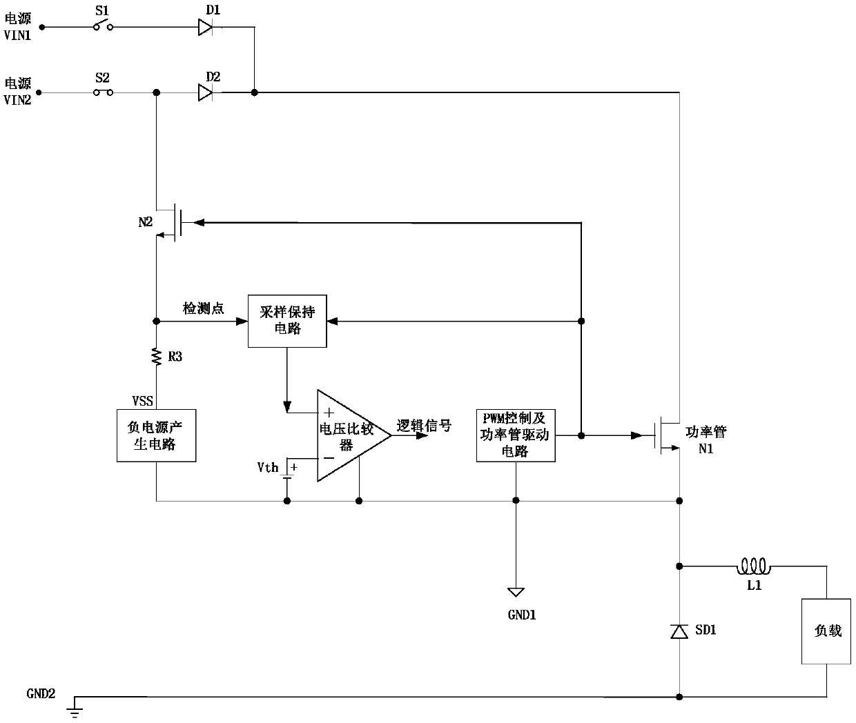
[0036] to combine figure 2 , which describes a specific embodiment of the present invention in detail, but does not limit the claims of the present invention in any way.

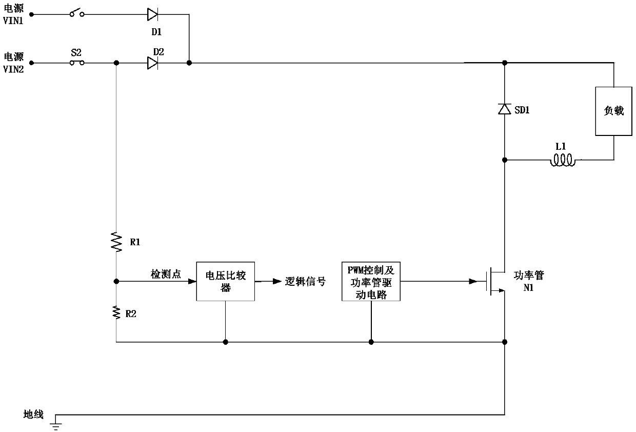
[0037] Such as figure 2 As shown, a power switch state detection circuit for floating ground BUCK switching power supply, floating ground BUCK switching power supply includes power VIN1, power VIN2, switch S1, switch S2, diode D1, diode D2, power tube N1 , Schottky diode SD1, inductor L1, PWM control and power tube drive circuit, the first ground wire GND1 and the second ground wire GND2, the power supply VIN1 is connected to one end of the switch S1, and the other end of the switch S1 is connected to the anode of the diode D1 , the power supply VIN2 is connected to one end of the switch S2, the other end of the switch S2 is connected to the anode of the diode D2, the gate of the power transistor N1 is connected to the output end of the PWM control and power transistor drive circuit, and the drain is resp...


PUM


Abstract

The invention relates to the technical field of power supply detection, in particular to a power switch state detection circuit for a floating ground wire BUCK type switch power supply. The floating ground wire BUCK type switch power supply comprises a power supply body VIN1, a power supply body VIN2, a switch S1, a switch S2, a diode D1, a diode D2, a power tube N1, a Schottky diode SD1, an inductor L1, a PWM control and power tube driving circuit, a first ground wire and a second ground wire. The power switch state detection circuit comprises an NMOS tube N2, a resistor R3, a sampling hold circuit, a negative power supply generating circuit and a voltage comparator. According to the power switch state detection circuit, the switch state is detected only in the conduction time period of the power tube, the leakage current of the diodes is small in the switch state detection time period, the detection resistance can be selected to be large, so that the power loss of the resistors is reduced, the working efficiency of a system is improved, meanwhile, the leakage current does not change along with the voltage of the power supply of the system, and the system does not generate errorsalong with the change of the voltage of the power supply.

Description

technical field [0001] The invention relates to the technical field of power supply detection, in particular to a power switch state detection circuit for a floating ground wire BUCK switching power supply. Background technique [0002] Such as figure 1 As shown, it is an existing power switch state detection circuit, wherein the power supply part includes power supply VIN1, power supply VIN2, switch S1, switch S2, diode D1, diode D2, diode SD1, inductor L1, power tube N1, detection circuit part Including resistor R1, resistor R2, voltage comparator, PWM control and power tube drive circuit, the detection circuit is used to detect the state of the switch S2 connected to the power supply VIN2, and output a logic signal. [0003] The system architecture of the power supply circuit is a BUCK type architecture. The circuit has two power supplies, the power supply VIN1 and the power supply VIN2 are selected and turned on by the switch S1 and the switch S2, and the PWM control an...

Claims


Application Information

Patent Timeline
IPC IPC(8): H02M3/158
CPCH02M3/158
Inventor 夏虎刘桂芝王冬峰
Owner WUXI LINLI SCI & TECH CO LTD
Why Eureka
Try Eureka