
Combined type fin with dovetail sealing grooves

A kind of sealing groove, combined technology, applied in the direction of jet propulsion device, rocket engine device, machine/engine, etc., can solve the problems of a certain amount of shaking, falling off, inconsistent height of the protruding mating surface, etc., so as to prevent the connecting bolt from entering the mating surface. possible, prevent drug leakage, and eliminate potential safety hazards

Inactive Publication Date: 2018-10-23
XIAN AEROSPACE CHEM PROPULTION PLANT
View PDF5 Cites 0 Cited by
  • Summary
  • Abstract
  • Description
  • Claims
  • Application Information

AI Technical Summary

Problems solved by technology

[0006] In the prior art, the fins mostly use flat grooves, and the width of the groove bottom of the flat groove is consistent with the width of the notch. In order to ensure that the O-ring is easy to install and placed in place, the groove width is generally slightly larger than the radial diameter of the O-ring. The final O-ring will shake to a certain extent, and there are hidden dangers of shifting and falling off during assembly
Different types of fins have different shapes, and the mating surface is mostly a curved surface. The wider slot width will lead to differences in the groove depth around the ring. Because the radial thickness of the O-ring is the same, the O-ring protrudes to the height of the mating surface. Inconsistent, there is a hidden danger of local drug leakage

Method used


Image

  • Combined type fin with dovetail sealing grooves
  • Combined type fin with dovetail sealing grooves

Examples


Embodiment Construction

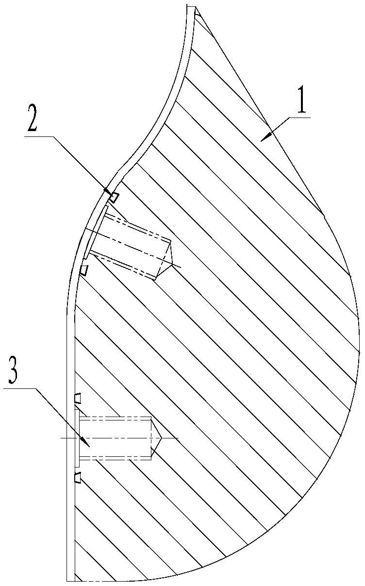
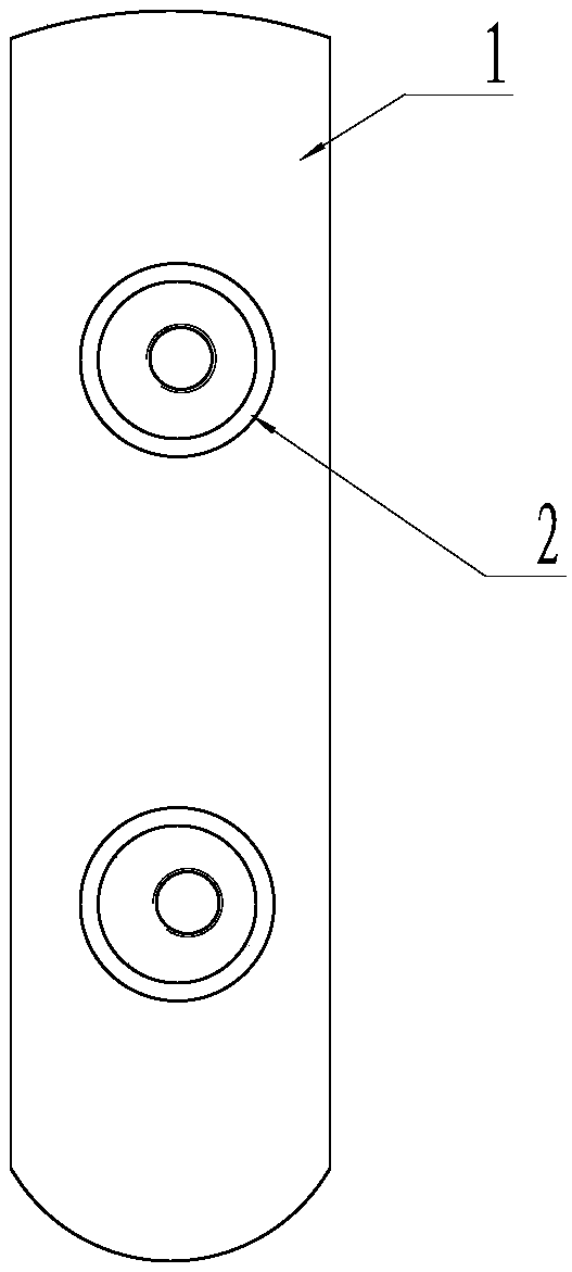
[0017] This embodiment is a combined fin with a dovetail sealing groove.

[0018] The mandrel fin 1 is a mandrel head fin of a certain type, and a plurality of fin connecting bolt holes 3 are distributed on the mating surface of the fin and the ferrule of the mandrel assembly head. An annular dovetail seal groove 2 is respectively processed on the outside of the circumference of each fin connecting bolt hole; the diameter of the inner wall of the annular dovetail sealing groove is 2 mm larger than the outer diameter of the fin connecting bolt hole, and the dovetail seal The grooved ring fits over the tab attachment bolt hole, forming a spill-proof barrier over the tab attachment bolt hole.

[0019] The O-ring of silicone rubber is placed in the dovetail seal groove. The width of the bottom of the dovetail sealing groove is larger than the width of the notch; the depth of the dovetail sealing groove is 3.5 mm, and the width of the bottom of the dovetail sealing groove is 4 mm;...


PUM


Abstract

The invention relates to a combined fin with dovetail sealing grooves. Bolt holes connected with head ferrules of a core mold assembly are distributed on the mating surface of a fin body, the annulardovetail sealing grooves are correspondingly processed outside the circumferences of the fin connecting bolt holes to clamp O-shaped sealing rings of silicon rubber, so that the O-shaped sealing ringscan effectively prevent medicine from leaking and entering a cladding shell to form new potential safety hazards and quality hazards, and the O-shaped sealing rings does not fall off. The diameter ofthe inner wall of each annular dovetail sealing groove is 2mm larger than the outer diameter of each fin connecting bolt hole, rings of the dovetail sealing grooves are nested on the fin connecting bolt holes, and thus spill-proof protective layers for the fin connecting bolt holes are formed. The application of the combined fin completely eliminates the possibility of propellant slurry enteringthe mating surface and entering connecting bolts, and eliminates potential safety hazards.

Description

technical field [0001] The invention belongs to the technical field of solid rocket motor charging, and relates to a sealing structure suitable for a combined mandrel. Background technique [0002] At present, the solid rocket motor rigid mandrel molding process is widely used, ranging from small standard test engines to large strategic model main engines, etc. The mandrel structure can be divided into integral structure or combined structure according to the pouring process. The components of the combined structure are connected by bolts, clamps or magnetic devices. Since the rigid mandrel itself is not easily deformed during the charging process, it does not chemically react with the propellant, and it has significant characteristics such as the reliability of the combustion chamber drug structure. , making it the main molding process of my country's solid engine combustion chamber grain. In years of application and continuous improvement, its design is becoming more and m...

Claims


Application Information

Patent Timeline
Patent Type & Authority Applications(China)
IPC IPC(8): F02K9/24F02K9/10
CPCF02K9/10F02K9/24
Inventor 曹巍郭宁刘雪松张海洋吴潇徐文华刘克文
Owner XIAN AEROSPACE CHEM PROPULTION PLANT
Learn More