Teaching experiment device for demonstrating performance of dynamic vibration absorber
A technology of dynamic vibration absorber and experimental device, applied in teaching models, instruments, educational appliances, etc., can solve the problem of not being able to display the influence of the quality, stiffness, and damping of dynamic vibration absorbers in many aspects, the damping being unadjustable, and the inability to compare passive vibration absorbers. , the characteristics of the hybrid vibration absorber, etc., to achieve the effect of simple structure, stable damping performance and easy installation
- Summary
- Abstract
- Description
- Claims
- Application Information
AI Technical Summary
Problems solved by technology
Method used
Image
Examples
Embodiment 1
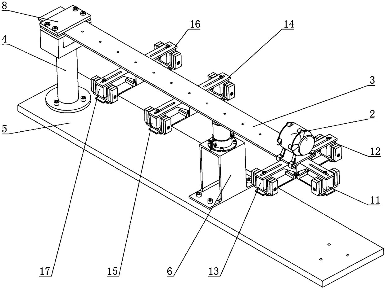
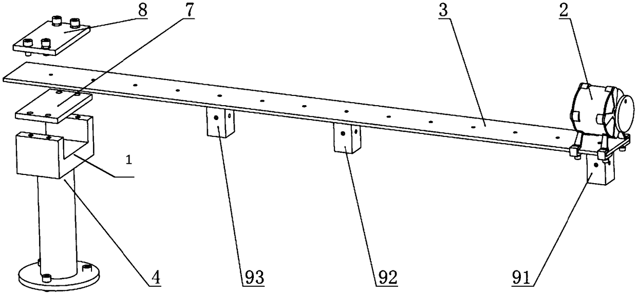
[0045] Such as Figure 1 to Figure 11 As shown, a teaching experimental device for performance demonstration of dynamic vibration absorber, including:
[0046] Bottom plate 5;
[0047] Column 4 is fixed on the base plate 5;
[0048] A cantilever beam 3, one end is fixed on the top of the column 4, the other end is a free end and a number of threaded holes are uniformly arranged along the length direction;
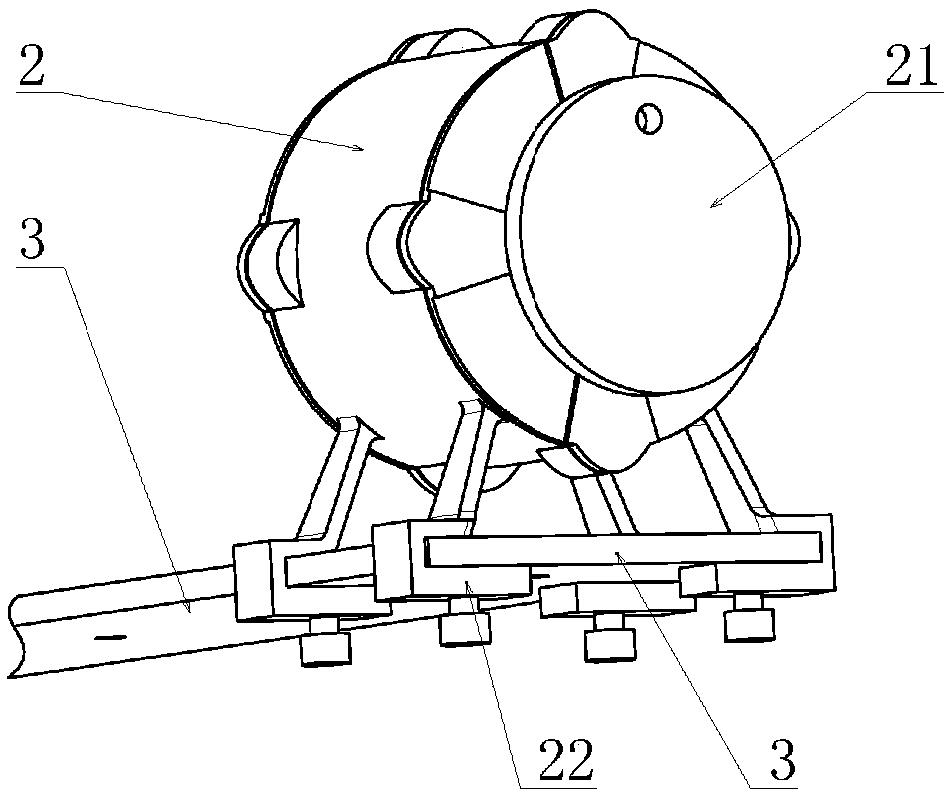
[0049] The eccentric motor 2 is fixedly arranged on the top surface of the cantilever beam 3 in an adjustable position;
[0050] The contact vibrator 6 is fixed on the bottom plate 5 and is located directly below the cantilever beam 3;
[0051] Seven dynamic absorbers and three dynamic absorber fixing blocks, the seven dynamic absorbers are respectively: the first dynamic absorber 11, the second dynamic absorber 12, the third dynamic absorber 13, the fourth dynamic absorber 14, The fifth dynamic vibration absorber 15, the sixth dynamic vibration absorber 16, and the sev...
Embodiment 2
[0065] refer to Figure 12 , on the basis of Embodiment 1, the contact exciter 6 is used as the excitation source of the system, and the cylinder 65 is adjusted upwards, so that the ejector rod above it contacts the lower surface of the cantilever beam 3, and a certain predetermined Pressure, the eccentric motor 2 is still installed on the free end of the cantilever beam 3, but does not work, only as an additional mass. The excitation method of the contact vibrator 6 adopts a frequency sweep method, such as setting from 0 to fe, wherein the value of fe is greater than the first-order natural frequency of the cantilever beam and less than the second-order natural frequency, and the first acceleration sensor 31 is used to measure the cantilever beam 3 The acceleration response signal of the free end before and after the installation of the dynamic vibration absorber, and the force signal of the contact vibration exciter 6 as the input signal, draw the amplitude-frequency charact...
Embodiment 3
[0073] refer to Figure 13 , on the basis of Embodiment 2, a second dynamic vibration absorber 12 is added to form a double dynamic vibration absorber system. At this time, the amplitude-frequency characteristic curve of the acceleration response after the installation of the dynamic vibration absorber is observed, and it has three peaks, which are Making the three peaks equal makes it possible to satisfy Equation 2,
[0074] Formula 2: gamma 1 =0.403(μ+0.131) -0.437 , gamma 2 =-0.72μ+1.03
[0075] where γ 1 and gamma 2 respectively represent the ratio of the first dynamic vibration absorber 11 and the second dynamic vibration absorber 12 to the natural frequency of the main system, and the relevant parameters and calculation methods in the formula are the same as those described in Embodiment 2.
[0076]Further, the third dynamic vibration absorber 13 is added, and its simplified dynamic model is as Figure 19 As shown, the observed amplitude-frequency characteristic c...
PUM
 Abstract
Description
Claims
Application Information
 - R&D
- Intellectual Property
- Life Sciences
- Materials
- Tech Scout
- Unparalleled Data Quality
- Higher Quality Content
- 60% Fewer Hallucinations
Browse by: Latest US Patents, China's latest patents, Technical Efficacy Thesaurus, Application Domain, Technology Topic, Popular Technical Reports.
© 2025 PatSnap. All rights reserved.Legal|Privacy policy|Modern Slavery Act Transparency Statement|Sitemap|About US| Contact US: help@patsnap.com


