
Automatic stacking device of iron core shearing production line

A production line and automatic technology, applied in the manufacture of inductors/transformers/magnets, electrical components, circuits, etc., can solve the problems of difficult to realize large-scale pick and place of sheet materials, high labor intensity of workers, low degree of automation, etc., to achieve structural Simple, small footprint and stable product quality

Pending Publication Date: 2018-10-23
CECEP XIAN QIYUAN MECHANICAL & EIECTRICAL EQUIP CO LTD
View PDF15 Cites 6 Cited by
  • Summary
  • Abstract
  • Description
  • Claims
  • Application Information

AI Technical Summary

Problems solved by technology

[0004] The purpose of the automatic stacking device of the iron core shearing production line provided by the present invention is to overcome that in the prior art, when producing transformer iron cores, the production line needs to go through a large number of manual stacking processes to complete the finished iron core, and the manual stacking process takes up a lot of manpower The problem of high labor intensity of resources and workers, low production efficiency, and unstable product quality; the second purpose is to overcome the problem of low automation in the manual stacking process in the prior art, and it is difficult to realize the problem of picking and placing large-scale pieces

Method used


Image

  • Automatic stacking device of iron core shearing production line
  • Automatic stacking device of iron core shearing production line
  • Automatic stacking device of iron core shearing production line

Examples


Embodiment 1

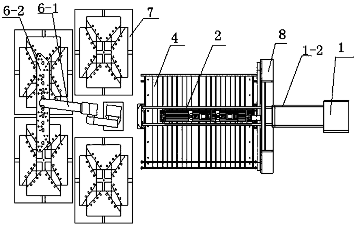
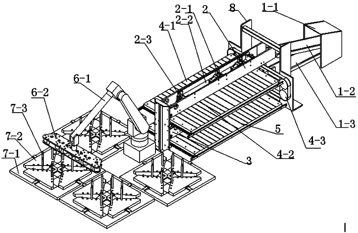
[0020] An automatic stacking device for an iron core shearing production line, including a frame body 8, and at least a material distribution device 1, an upper layer conveying device 2, a lower layer conveying device 3, an upper layer receiving platform 4, a lower layer receiving platform 5, a stacking The robot hand 6 and the multi-station stacking platform 7, the upper conveying device 2, the upper material receiving platform 4, the lower conveying device 3 and the lower material receiving platform 5 are sequentially connected to the frame body 8 from top to bottom, and the right side of the frame body 8 The side is connected to the material distribution device 1 and the output end of the material distribution device 1 is respectively connected to the input end of the upper layer conveying device 2 and the input end of the lower layer conveying device 3. The left side of the frame body 8 is provided with a stacking robot 6 and a multi-station stacking machine. The platform 7...

Embodiment 2

[0022] like Figure 1-3 As shown, an automatic stacking device for an iron core shearing production line includes a frame body 8, and at least includes a material distribution device 1, an upper layer conveying device 2, a lower layer conveying device 3, an upper layer receiving platform 4, and a lower layer receiving platform 5 , the stacking robot arm 6 and the multi-station stacking table 7, the upper conveying device 2, the upper material receiving platform 4, the lower conveying device 3 and the lower material receiving platform 5 are sequentially connected on the frame body 8 from top to bottom, and the frame body The right side of 8 is connected to the material distribution device 1 and the output end of the material distribution device 1 is respectively connected to the input end of the upper layer conveying device 2 and the input end of the lower layer conveying device 3, and the left side of the frame body 8 is provided with a stacking robot arm 6 and a multiplexer. ...

Embodiment 3

[0025] The material distribution device 1 at least includes a material distribution flap 1-1, an upper belt conveyor 1-2 and a lower belt conveyor 1-3, and the material distribution flap 1-1 is respectively connected to the input of the upper belt conveyor 1-2. and the input end of the lower belt conveyor 1-3, the output end of the upper belt conveyor 1-2 is connected to the input end of the upper conveyor 2, and the output end of the lower belt conveyor 1-3 is connected to the input end of the lower conveyor 3 . The material distribution flap 1-1 of the material distribution device 1 divides the sheet material into upper and lower layers according to the sheet shape. The belt conveyor 1-3 transports the sheet material to the lower conveying device 3, which has a high degree of automation.

[0026] Described upper conveying device 2 and lower conveying device 3 all at least comprise conveying belt conveyor 2-1, movable magnetic plate 2-2 and positioning signaling switch 2-3, ...


PUM


Abstract

The invention belongs to the technical field of professional electrician equipment, and particularly relates to an automatic stacking device of an iron core shearing production line. The automatic stacking device comprises a frame body, and also at least comprises a material distribution device, an upper-layer conveying device, a lower-layer conveying device, an upper-layer material receiving table, a lower-layer material receiving table, a stacking machine hand, a multi-station stacking table. The upper-layer conveying device, the upper-layer material receiving table, the lower-layer conveying device and the lower-layer material receiving table are sequentially connected to the frame body from top to bottom; the right side of the frame body is connected with the material distributing device, and the stacking machine hand and the multi-station stacking table are arranged on the left side of the frame body; the multi-station stacking table is located below the stacking machine hand. Theproblems that in an existing production line, iron core finished products can be completed through a lot of manual stacking procedures, many manpower resources are occupied by the manual stacking procedures, the labor intensity of workers is high, the production efficiency is low, and the product quality is unstable are solved. The device can achieve quick, orderly and regular stacking, manual operation is replaced, and the manpower resources can be saved.

Description

technical field [0001] The invention belongs to the technical field of professional electrical equipment, and in particular relates to an automatic stacking device for an iron core shearing production line. Background technique [0002] In the production of transformer iron cores in the electrical industry, a large number of CNC cross-cut production lines are used. The stacking method of the traditional production line is the feeding type, the more advanced one is the automatic material sorting type, and the most advanced is the bottom threading needle stacking type. After that, a large number of The finished iron core can only be completed by manual stacking process. [0003] At present, the manual stacking process takes up a lot of human resources, the labor intensity of workers is high, the production efficiency is low, and the product quality is unstable. If the production line is required to have a high degree of automation, less human resources, high production effici...

Claims


Application Information

Patent Timeline
Patent Type & Authority Applications(China)
IPC IPC(8): H01F41/02
CPCH01F41/0233
Inventor 董涛肖伟刘利军崔有成
Owner CECEP XIAN QIYUAN MECHANICAL & EIECTRICAL EQUIP CO LTD
Learn More