Aluminum alloy and fastener member
A technology for fastening parts and aluminum alloys, applied in the direction of threaded fasteners, connecting components, screws, etc., can solve problems such as lightweight obstacles, and achieve the effect of excellent strength and toughness
- Summary
- Abstract
- Description
- Claims
- Application Information
AI Technical Summary
Problems solved by technology
Method used
Image

Examples
Embodiment approach 1
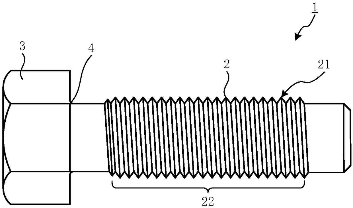
[0024] figure 1 It is a side elevational view showing the structure of the fastening member according to the first embodiment of the present invention. figure 1 The fastening member 1 shown is a bolt (one outer threaded member) made of an aluminum (Al) alloy. The fastening member 1 includes a shaft portion 2 having a cylindrical shape; a head 3, which is disposed in the axial direction of the shaft portion 2 ( figure 1 One end of the left and right direction; and the neck 4 constitute the boundary between the shaft portion 2 and the head 3. The shaft portion 2 has a threaded portion 22 which is formed with a threaded teeth 21. Further, the shape (hex head type) of the head 3 is simply one example, or other shapes (hexa-angle type, flat head type, flat head type, flat head type, flat top cylindrical head type, etc.).
[0025] The fastening member 1 is made of an aluminum alloy containing silicon (Si), copper (Cu), manganese (Mn), magnesium (Mg) and zinc (Zn), and the margin is fro...
Embodiment approach 2
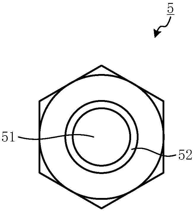
[0038] figure 2 It is a top plan view showing the structure of the fastening member according to the second embodiment of the present invention. figure 2 The fastening member 5 shown is a nut (one of the internal threaded components) made of the above aluminum alloy. The fastening member 5 is present in a hollow cylindrical shape, and a thread 52 is formed in the inner surface of the aperture 51 formed in the central portion. in addition, figure 2 The shape (hex nut) of the fastening member 5 is only an example, and it is also possible to be implemented as a nut (flange nut, cover nut, long nut, etc.) having other shapes.
[0039] The fastening member 5 is carried out, which is formed using the above aluminum alloy. The fastening member 5 is formed by brushed molding by a rod-shaped member made of the aluminum alloy, a core tubing process and a cold head processing or the like.
[0040] According to the first embodiment of the present invention described above, by using Si contai...
Embodiment approach 3
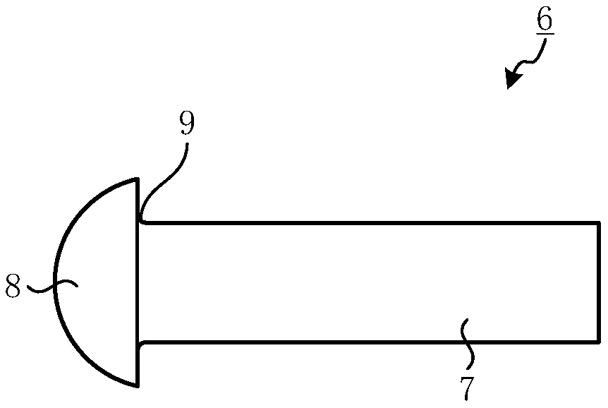
[0042] image 3 It is a side view showing the structure of the fastening member according to the third embodiment of the present invention. image 3 The fastening member 6 is a rivet made of the above aluminum alloy. The fastening member 6 includes: the shaft portion 7, which is cylindrical; head 8, which is disposed at the height direction of the cylinder constituting the shaft portion 7 ( image 3 One end of the left and right direction; and the neck 9 constitute the boundary between the shaft portion 7 and the head 8. in addition, image 3 The shape (round head type) of the head 8 shown is not only one example, with other shapes (flat head type, etc.).
[0043] The fastening member 6 can be formed by bridging processing and cold heading processing by a rod member made of the above aluminum alloy.
[0044] According to the first embodiment of the present invention described above, by using Si containing 0.7% or more, 0.5% or more of 2.8% or less Mn, 0.6% or more 1.6% Mg and 0.1. % ...
PUM
 Abstract
Description
Claims
Application Information
 - R&D
- Intellectual Property
- Life Sciences
- Materials
- Tech Scout
- Unparalleled Data Quality
- Higher Quality Content
- 60% Fewer Hallucinations
Browse by: Latest US Patents, China's latest patents, Technical Efficacy Thesaurus, Application Domain, Technology Topic, Popular Technical Reports.
© 2025 PatSnap. All rights reserved.Legal|Privacy policy|Modern Slavery Act Transparency Statement|Sitemap|About US| Contact US: help@patsnap.com