Supercharge Your Innovation With Domain-Expert AI Agents!

Cylinder liner and Anti-polishing ring

A technology of cylinder liner and wear-resistant ring, applied in the field of wear-resistant ring, can solve the problem of limited service life of pressure sensor, and achieve the effect of increasing service life

Active Publication Date: 2018-10-23
WARTSILA FINLAND OY
View PDF7 Cites 0 Cited by
  • Summary
  • Abstract
  • Description
  • Claims
  • Application Information

AI Technical Summary

Problems solved by technology

The disadvantage of direct pressure monitoring is that the life of the pressure sensor is limited due to the high temperatures and vibrations occurring in the cylinder head

Method used


Image

  • Cylinder liner and Anti-polishing ring
  • Cylinder liner and Anti-polishing ring
  • Cylinder liner and Anti-polishing ring

Examples


Embodiment Construction

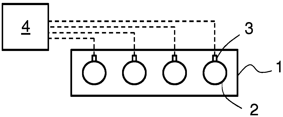
[0015] exist figure 1 An internal combustion engine 1 with a cylinder pressure monitoring arrangement is schematically shown in . The engine 1 is a large piston engine, such as a main or auxiliary engine of a ship or an engine used to generate electricity in a power plant. The cylinder diameter of the engine 1 is at least 150 mm. exist figure 1 , four cylinders 2 are shown. However, the engine 1 may comprise any reasonable number of cylinders 2 which may eg be arranged in line or in a V-shaped configuration. In order to monitor the pressure in the cylinders 2 , each cylinder of the engine 1 is provided with a pressure sensor 3 . The pressure sensor 3 is arranged to directly measure the cylinder pressure. Thus, each pressure sensor 3 is exposed to the cylinder pressure in the corresponding cylinder 2 . Each pressure sensor 3 is connected to a control unit 4 .

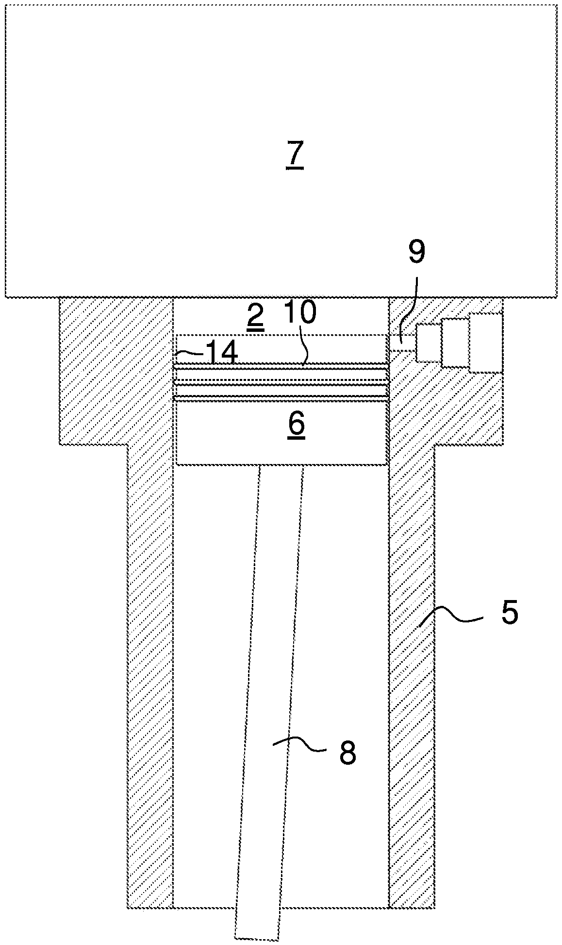
[0016] figure 2 A simplified cross-sectional view of a cylinder liner 5 according to an embodiment of the inv...


PUM


Abstract

A cylinder liner (5) for forming a cylinder (2) of a piston engine (1) comprises a through hole (9), which is configured to allow transmission of pressure from the cylinder (2) to a pressure sensor (3) and arranged in the wall of the cylinder liner (5) at such a height that when the cylinder liner (5) is mounted in an engine (1) for forming a cylinder (2) and a piston (6) inside the cylinder (2) is at top dead center, the hole (9) opens inside the cylinder (2) at a location that is above all the piston rings (10) of the piston (6).

Description

technical field [0001] The invention relates to a cylinder liner according to the preamble of claim 1 . The invention also relates to a wear ring for a cylinder liner as defined in the preambles of the other independent claims. Background technique [0002] Large internal combustion engines such as ships and power plant engines are often provided with means for monitoring cylinder pressure. Cylinder pressure is measured either directly using a pressure sensor exposed to in-cylinder pressure or using a strain gauge, force sensor or similar device that monitors deformation and displacement of engine block components. If direct pressure measurement is used, the pressure sensor is typically arranged in the cylinder head of the engine. A disadvantage of direct pressure monitoring is that the life of the pressure sensor is limited due to the high temperatures and vibrations occurring in the cylinder head. Contents of the invention [0003] It is an object of the present inven...

Claims


Application Information

Patent Timeline
Patent Type & Authority Applications(China)
IPC IPC(8): F02B77/08F02F1/00
CPCF02F2001/006F02F1/004F02B77/085
Inventor A·奥斯特T·哈格达尔S·英格T·埃马乌斯
Owner WARTSILA FINLAND OY
Features
  • R&D
  • Intellectual Property
  • Life Sciences
  • Materials
  • Tech Scout
  • Unparalleled Data Quality
  • Higher Quality Content
  • 60% Fewer Hallucinations
Learn More