Light guide device, light guide method, and ld module
A light guide device and light beam technology, which is applied in semiconductor laser optical devices, semiconductor lasers, optics, etc., can solve problems such as the limit of reliability improvement, and achieve the effect of improving reliability
- Summary
- Abstract
- Description
- Claims
- Application Information
AI Technical Summary
Problems solved by technology
Method used
Image

Examples
no. 1 approach 〕
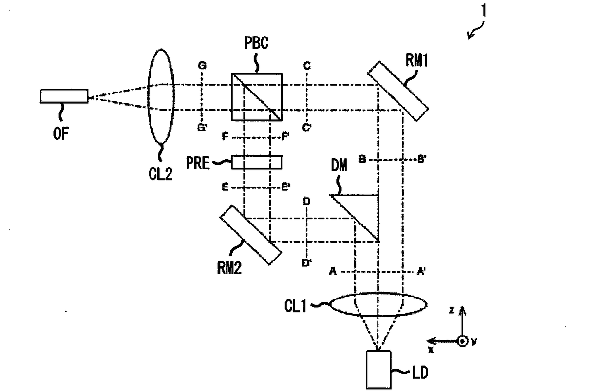
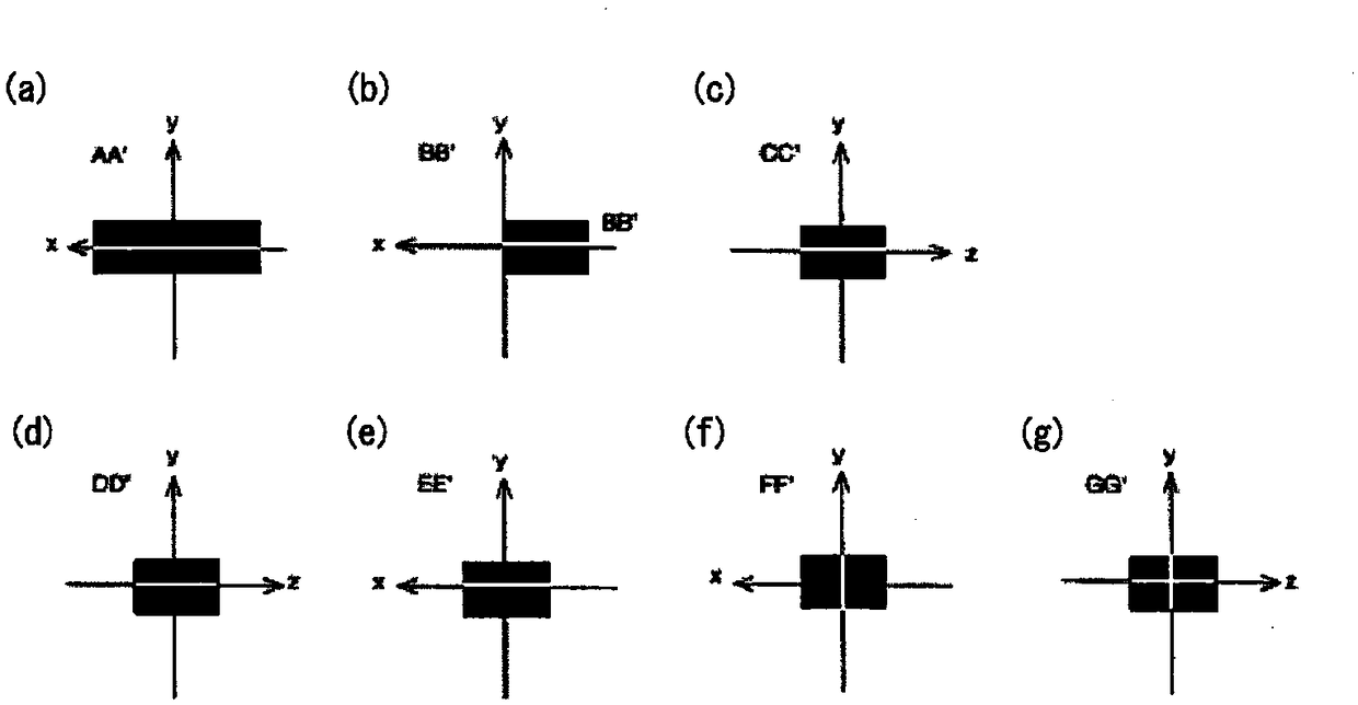
[0032] refer to figure 1 and figure 2 The LD module 1 according to the first embodiment of the present invention will be described. figure 1 It is a plan view showing the structure of the LD module 1 . figure 2 It is a cross-sectional view showing a beam profile of a laser beam, a partial beam, or a partial beam group in each part of the LD module 1 .
[0033] Such as figure 1 As shown, the LD module 1 includes a laser diode LD, a collimator lens CL1, a split optical system 11 (a split mirror DM), a composite optical system 12 (a first mirror RM1, a second mirror RM2, a polarization rotation element PRE, a polarization beam combiner PBC), condenser lens CL2 and optical fiber OF. In the LD module 1 , the collimator lens CL1 , the splitting optical system 11 , the combining optical system 12 , and the condenser lens CL2 constitute a light guide device that guides laser light output from the laser diode LD to the optical fiber OF.
[0034] The laser diode LD outputs a lase...
no. 2 approach 〕
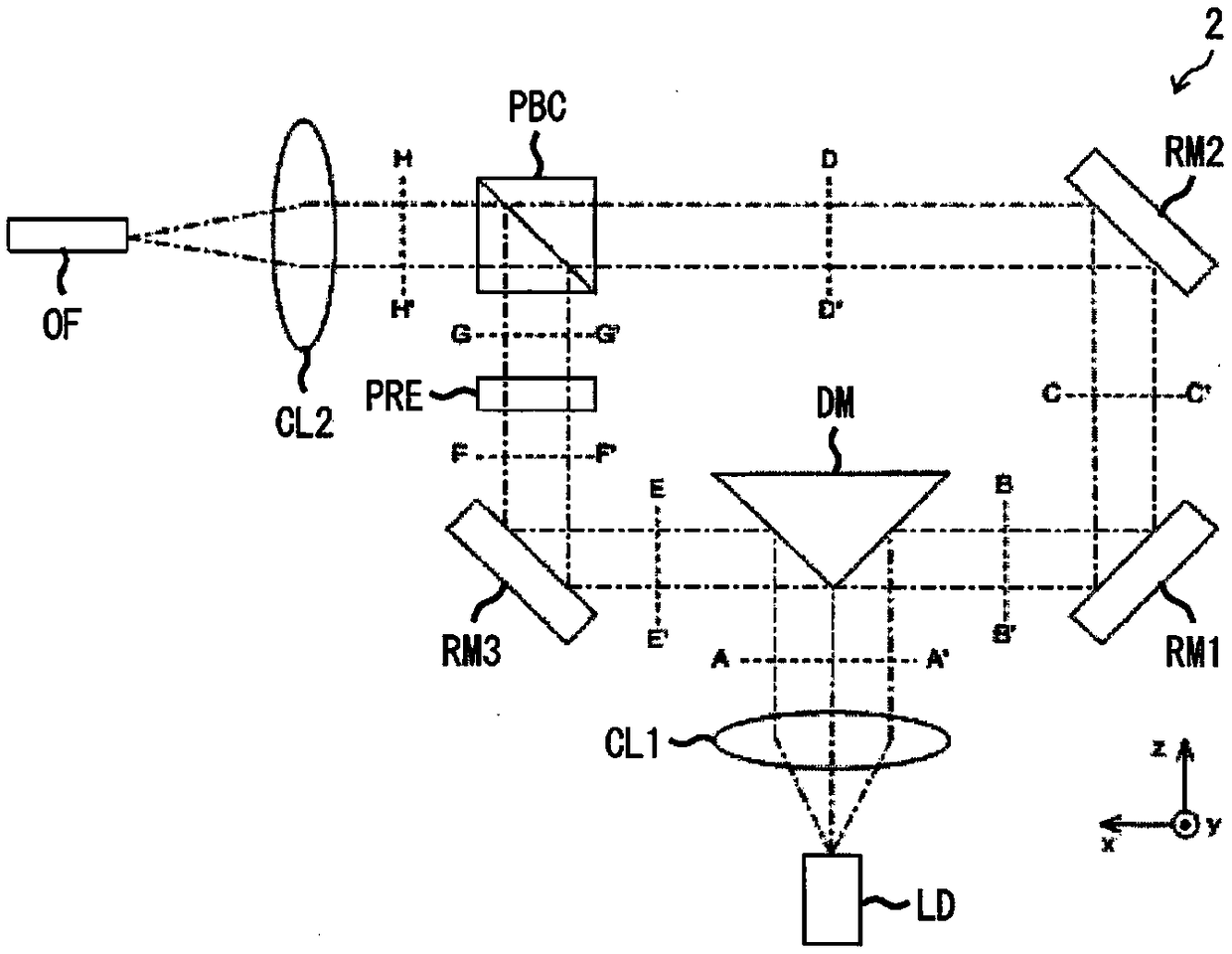
[0060] refer to image 3 and Figure 4 The LD module 2 of the second embodiment of the present invention will be described. image 3 It is a plan view showing the structure of the LD module 2 . Figure 4 It is a cross-sectional view showing a beam profile of a laser beam, a partial beam, or a partial beam group in each part of the LD module 2 .
[0061] Such as image 3 As shown, the LD module 2 includes a laser diode LD, a collimator lens CL1, a split mirror DM, a first mirror RM1, a second mirror RM2, a third mirror RM3, a polarization rotation element PRE, a polarization beam combiner PBC, Condenser lens CL2 and optical fiber OF. In the LD module 2, the collimator lens CL1, the split mirror DM, the first mirror RM1, the second mirror RM2, the third mirror RM3, the polarization rotation element PRE, the polarization beam combiner PBC and the condenser lens CL2 constitute A light guiding device that guides the laser light output from the laser diode LD to the optical fib...
no. 3 approach 〕
[0085] refer to Figure 5 and Figure 6 The LD module 3 according to the third embodiment of the present invention will be described. Figure 5 Among them, (a) is a plan view showing the configuration of the LD module 3 , and (b) is a perspective view showing the configuration of the double mirror DRM included in the LD module 3 . Figure 6 It is a cross-sectional view showing a beam profile of a laser beam, a partial beam, or a partial beam group in each part of the LD module 3 .
[0086] Such as Figure 5 As shown in (a), the LD module 3 includes a laser diode LD, a collimator lens CL1, a split mirror DM, a first mirror RM1, a second mirror RM2, a third mirror RM3, a fourth mirror RM4, a double Mirror DRM, condenser lens CL2 and optical fiber OF. In the LD module 3, the collimator lens CL1, the split mirror DM, the first mirror RM1, the second mirror RM2, the third mirror RM3, the fourth mirror RM4, the double mirror DRM and the condenser lens CL2 constitute A light gui...
PUM
 Abstract
Description
Claims
Application Information
 - R&D Engineer
- R&D Manager
- IP Professional
- Industry Leading Data Capabilities
- Powerful AI technology
- Patent DNA Extraction
Browse by: Latest US Patents, China's latest patents, Technical Efficacy Thesaurus, Application Domain, Technology Topic.
© 2024 PatSnap. All rights reserved.Legal|Privacy policy|Modern Slavery Act Transparency Statement|Sitemap