A hoisting device for welding and manufacturing high-voltage electrical boxes of EMUs

A hoisting device and electrical box technology, applied in the direction of transportation and packaging, load hanging components, etc., can solve the problems that are difficult to achieve simple, fast, reliable and safe hoisting and disassembly of the welded structure skeleton of the high-voltage box, and achieve simple structure, Improve work efficiency and reduce work intensity

Active Publication Date: 2019-11-26
BEIJING CED RAILWAY ELECTRIC TECH
View PDF5 Cites 0 Cited by
  • Summary
  • Abstract
  • Description
  • Claims
  • Application Information

AI Technical Summary

Problems solved by technology

[0004] Under the condition of limited welding workshop space and equipment, it is difficult to realize simple, fast, reliable and safe hoisting and dismantling of the high-voltage box welding structure skeleton

Method used


Image

  • A hoisting device for welding and manufacturing high-voltage electrical boxes of EMUs
  • A hoisting device for welding and manufacturing high-voltage electrical boxes of EMUs
  • A hoisting device for welding and manufacturing high-voltage electrical boxes of EMUs

Examples


specific Embodiment approach

[0014] The hoisting device for the welding manufacture of the high-voltage electrical box of the multiple train set of the present invention, its preferred specific implementation mode is:

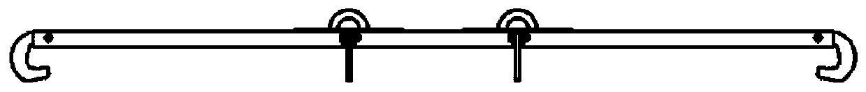
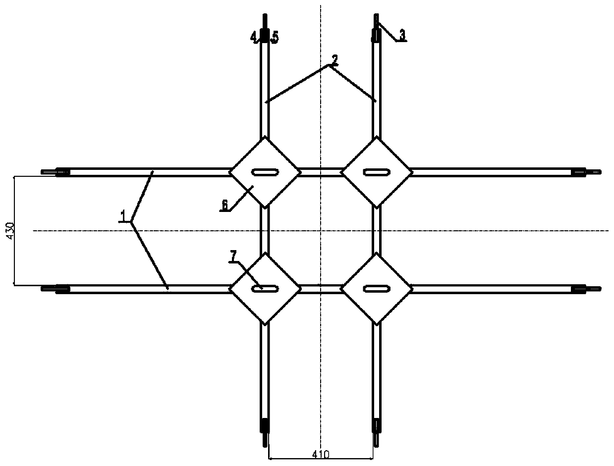
[0015] It includes two sets of support arms one set horizontally and two sets of support arms two set vertically. Ribs and lifting lugs are respectively provided at the intersections of the arms, and hooks are respectively provided at the two ends of the first support arm and the second support arm.

[0016] The two ends of the support arm 1 and the support arm 2 are provided with rotation slots and installation holes, and the hooks are installed in the rotation slots and connected with the installation holes through bolts and nuts.

[0017] The hook is C-shaped, and the hook tips of the hooks at both ends of the same support arm are arranged symmetrically inward.

[0018] The hook is kept in an unlocked state after being rotated outward and upward around the bolt; the hook is kept in a l...

specific Embodiment

[0022] Specific examples, such as figure 1 , figure 2 , image 3 , Figure 4 Shown:

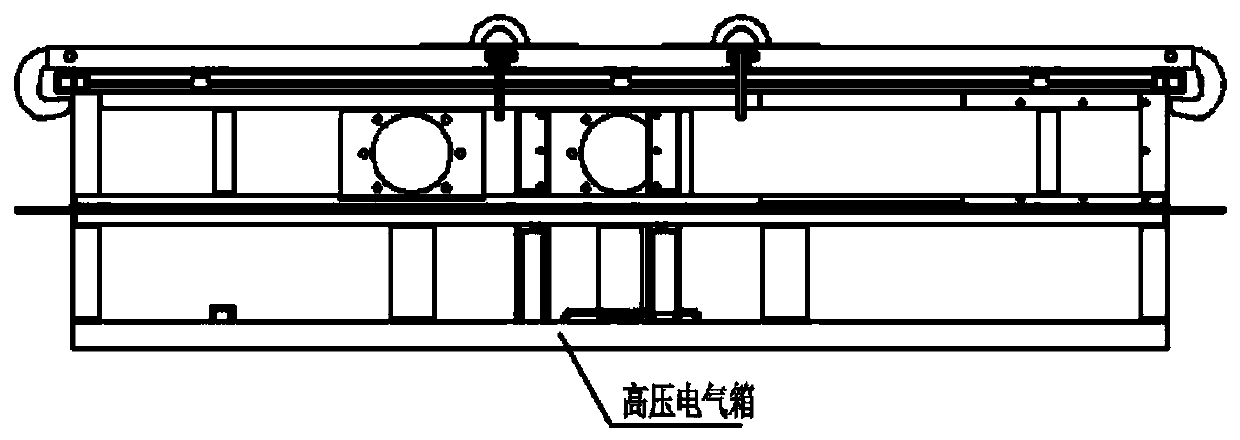
[0023] The hoisting device for the welding and manufacturing of the high-voltage electrical box of the EMU includes two sets of support arms 1, two sets of support arms 2, eight sets of hooks 3, eight sets of bolts 4 and nuts 5, four sets of ribs 6, and four sets of lifting lugs 7 .

[0024] The support arm-1 adopts a 40mm×30mm×3mm stainless steel rectangular pipe;

[0025] There are 50mm×15mm grooves on the plane with a width of 30mm at both ends; ¢10mm through holes are opened on the sides of 40mm at both ends;

[0026] The support arm two 2 adopts a 40mm×30mm×3mm stainless steel rectangular pipe;

[0027] There are 50mm×15mm grooves on the plane with a width of 30mm at both ends; ¢10mm through holes are opened on the sides of 40mm at both ends;

[0028] The two groups of support arms 1 are parallel to each other; the two groups of support arms 2 are parallel to each other; the supp...


PUM


Abstract

The invention discloses a hoisting device for D-series high-speed train high-voltage electrical box welding and manufacturing. The hoisting device comprises two transversely-arranged first supportingarms and two longitudinally-arranged second supporting arms. The two transversely-arranged first supporting arms and the two longitudinally-arranged second supporting arms are mutually crossed to forma #-shaped structure. Rib plates and lifting lugs are arranged at the crossed parts of the supporting arms. Lifting hooks are arranged at the two ends of the first supporting arms and the two ends ofthe second supporting arms. After the lifting hooks rotate towards the upper portion of the outer side, the unlocking state is kept. After the lifting hooks rotate downwards, the position locking state is kept. The structure is simple, convenience and rapidness are achieved, the box body structure characteristics are ingeniously utilized, and hoisting and dismounting of a high-voltage box weldingstructure framework can be simply, rapidly, reliably and safely conducted under the limited welding plant space and equipment conditions.

Description

technical field [0001] The invention relates to a hoisting technology, in particular to a hoisting device for welding and manufacturing a high-voltage electrical box of an EMU. Background technique [0002] The high-voltage electrical box is a box that integrates and builds high-voltage electrical equipment on the roof of the EMU. It has become a mainstream application product for EMUs because it solves the phenomenon of high-voltage discharge caused by rain, snow, ice, fog and other weather. [0003] The welding skeleton of the high-voltage electrical box is 2200mm×1700mm×506mm in size and weighs hundreds of kilograms. It is made of aluminum alloy profiles through welding. The final welding is carried out on the general assembly welding turning tire with a height of 1200mm from the ground. After the box body is welded, the box needs to be removed from the general assembly welding turning tire and enter the next process. [0004] Under the conditions of limited welding work...

Claims


Application Information

Patent Timeline
Patent Type & Authority Patents(China)
IPC IPC(8): B66C1/28
CPCB66C1/28
Inventor 黄思俊徐玉峰郁焕武吴玉启
Owner BEIJING CED RAILWAY ELECTRIC TECH
Why Eureka
Try Eureka