Shallow-burying exposure construction method applicable to hard rock tunnel with extra large fracture surface

A technology with super large section and construction method, which is applied in tunnels, tunnel linings, earthwork drilling and mining, etc., can solve problems such as poor applicability, environmental damage, and large excavation volume, and achieve the goal of reducing construction costs, reducing pollution, and speeding up construction Effect

Active Publication Date: 2018-10-26
CHINA TIESIJU CIVIL ENG GROUP +1
View PDF7 Cites 1 Cited by
  • Summary
  • Abstract
  • Description
  • Claims
  • Application Information

AI Technical Summary

Problems solved by technology

However, these methods often bring about the problems of large excavation volume and environmental damage caused by grouting. For complex terrain conditions, strict environmental requirements, and tight construction schedules, the above methods are less applicable

Method used


Image

  • Shallow-burying exposure construction method applicable to hard rock tunnel with extra large fracture surface
  • Shallow-burying exposure construction method applicable to hard rock tunnel with extra large fracture surface
  • Shallow-burying exposure construction method applicable to hard rock tunnel with extra large fracture surface

Examples


example 1

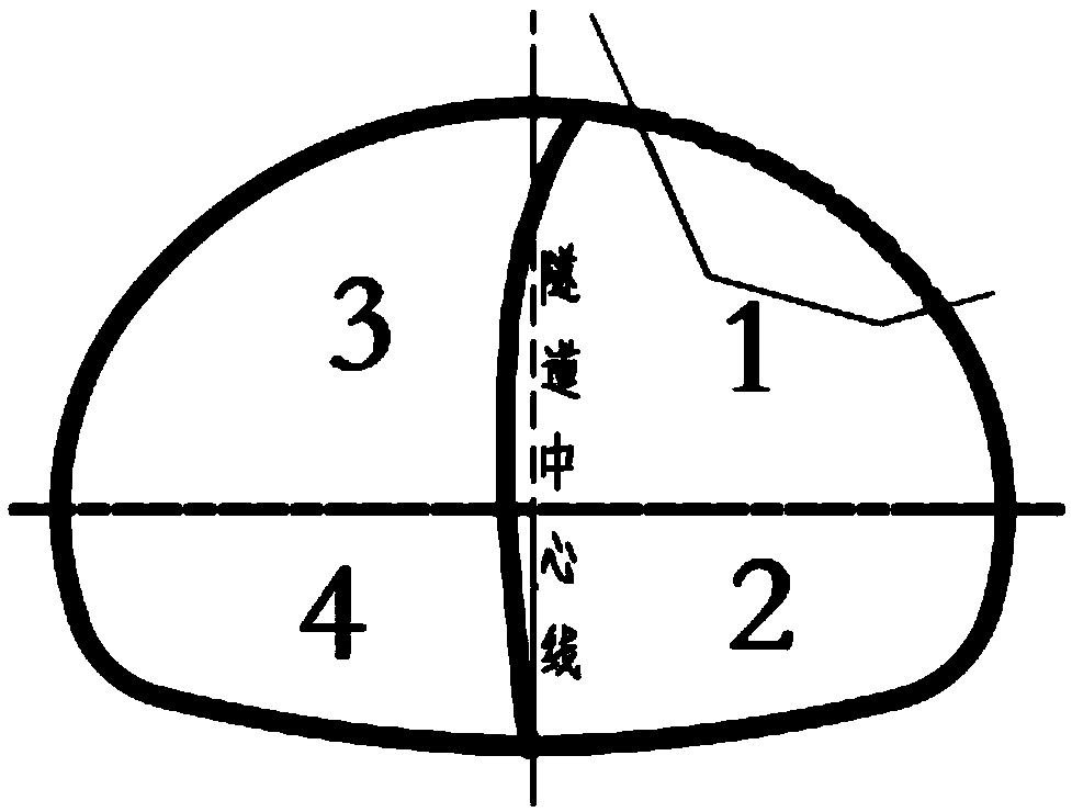
[0027] Example 1: if figure 1 As shown, the CD method is used for construction.

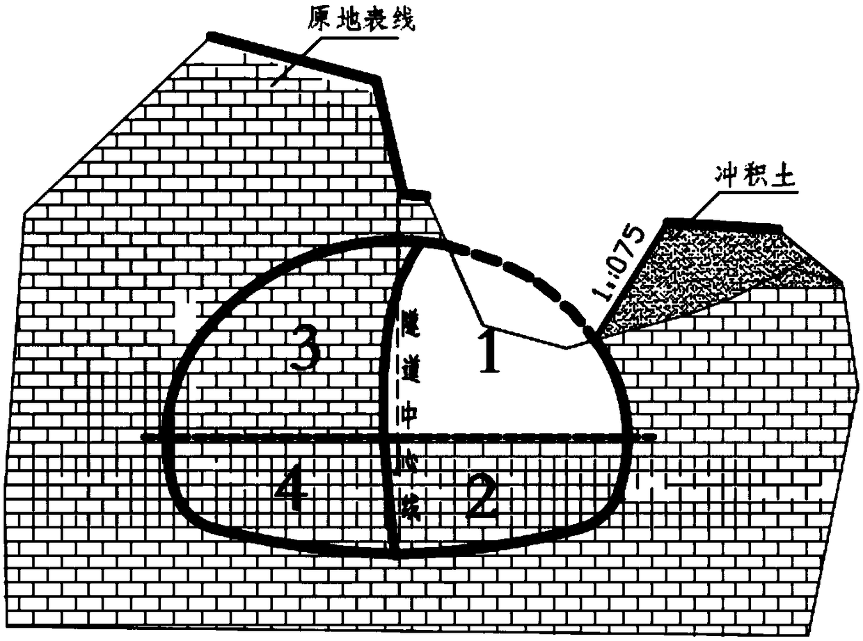
[0028] The section of the tunnel is divided into 4 parts, which are respectively described as upper right part - upper right pilot tunnel (first excavation part), lower right part - lower right pilot tunnel (second excavation part), upper left part - upper left pilot tunnel (third excavation part). excavation part), lower left part-lower left pilot tunnel (fourth excavation part), excavation shall be carried out in sequence according to the numerical sequence, see Figure 3 ~ Figure 8 .

[0029] First, remove the weak soil within the influence range of the exposed surface, and protect the slope of the weak soil with anchor net spraying;

[0030] Excavate the first excavation part, then support the first support part; excavate the second excavation part, and then support the second support part; backfill the tunnel arch with soil pressure Excavate the third excavation part, then support the thi...

example 2

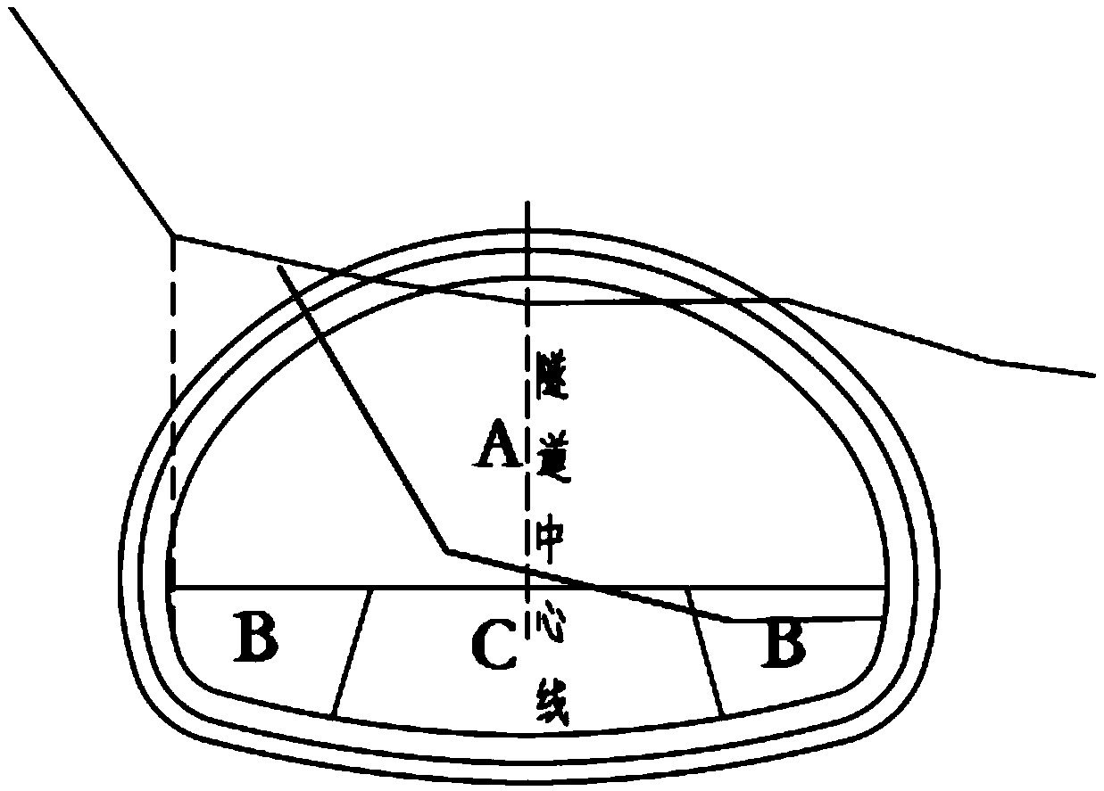
[0032] Example 2: if figure 2 As shown, the step method is used for construction.

[0033] The section of the tunnel is divided into three parts, which are described as upper part-upper step (excavation part A), left and right parts-lower step left and right pilot tunnels (excavation part B), middle part-lower step core soil (excavation part C). Excavation Department), excavation shall be carried out sequentially according to the numerical sequence, see the specific excavation Figure 9 ~ Figure 14 .

[0034] First, remove the weak soil within the influence range of the exposed surface, and protect the slope of the weak soil with anchor net spraying;

[0035] First carry out backfilling; excavate the A-th excavation part, and then support the A-th support part; excavate the B-th excavation part, and then support the B-th support part; The excavation part C is excavated, and then the support part C is supported; during the whole excavation process, the excavation part B lag...


PUM


Abstract

The invention provides a shallow-burying exposure construction method applicable to a hard rock tunnel with an extra large fracture surface. The excavated volume of soft soil exposed on the earth surface is compared with that of a first excavation part formed by means of a CD method, cover arch construction is conducted if the excavated volume of the soft soil is higher than that of the first excavation part, a benching tunneling method is adopted for excavation, and if the excavated volume of the soft soil is not higher than that of the first excavation part, the CD method is adopted for excavation; according to the CD method, the whole process is divided into four steps for excavation, correspondingly there are four parts to be supported, and backfill of the ground needs to be conductedin time after a second excavation part is completed; according to the benching tunneling method, the whole process is divided into three steps for excavation, and backfill of the earth surface is conducted after excavation of an upper bench is finished; side slopes of excavated soft soil are supported in time through bolt mesh spraying. The open excavation amount and grouting amount of the groundare decreased under the situation that the fracture surface of the tunnel is extra large, the adaptability is high, environmental pollution is small, the excavation speed is high, and economic benefits are remarkable.

Description

technical field [0001] The invention relates to the excavation field of super-large-section rock blasting in tunnels and underground structures, in particular to a shallow-buried and exposed construction method suitable for super-large-section hard rock tunnels. Background technique [0002] According to data, with the further development of my country's transportation industry, a large number of large-section tunnel projects have emerged. The current construction of shallow-buried and exposed large-section tunnels mainly includes open-cut method, cover-excavation method, backfilling poor-mix backpressure method, and backfilling grouting reinforcement method. The main purpose is to pass Eliminate the influence of surrounding rock or strengthen the self-stabilization ability of surrounding rock to achieve construction stability and safety during tunnel excavation. However, these methods often bring about the problems of large excavation volume and environmental damage caused...

Claims


Application Information

Patent Timeline
IPC IPC(8): E21D9/14E21D9/04E21D9/00E21D11/10E21D20/00
CPCE21D9/001E21D9/04E21D9/14E21D11/10E21D20/00
Inventor 余诚孟永立陈文尹杜江山隗志远邢彪姚大闯冯冀蒙章育坤
Owner CHINA TIESIJU CIVIL ENG GROUP
Why Eureka
Try Eureka