Synchronous switched reluctance motor

A reluctance motor and synchronous switch technology, which is applied to synchronous motors, electric components, electrical components, etc. for single-phase current, can solve the problems of complex rotor structure of synchronous reluctance motors, large torque pulsation of switched reluctance motors, convex problems such as extremely small, to achieve the effect of simple structure, small current pulsation, and avoidance of Lq increase

Pending Publication Date: 2018-10-26
北京动力京工科技有限公司
View PDF0 Cites 3 Cited by
  • Summary
  • Abstract
  • Description
  • Claims
  • Application Information

AI Technical Summary

Problems solved by technology

[0005] To sum up, in order to solve the shortcomings of the switched reluctance motor, such as large torque ripple and high noise, but also to solve the problems of the synchronous reluctance motor's rotor structure and small salient pole ratio, it is necessary to improve the structure of the motor

Method used


Image

  • Synchronous switched reluctance motor
  • Synchronous switched reluctance motor
  • Synchronous switched reluctance motor

Examples


Embodiment 1

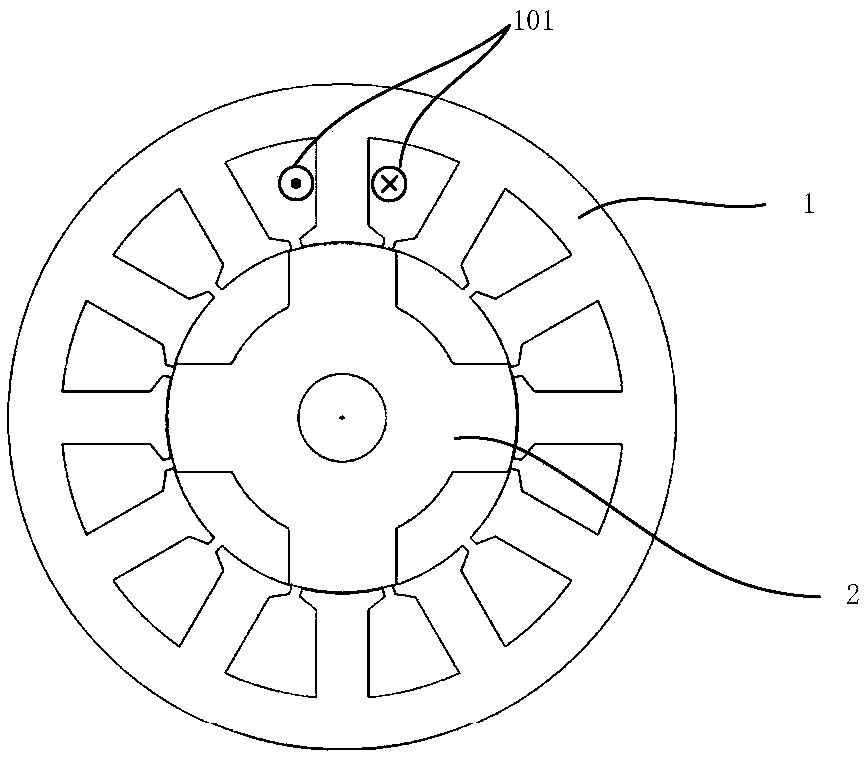
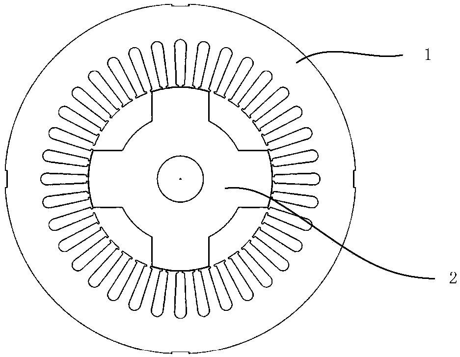
[0043] Synchronous switched reluctance motor with radial magnetic circuit, figure 1 Schematic diagram of centralized winding for synchronous switched reluctance motor; figure 2 Schematic diagram of cogging using distributed windings for a synchronous switched reluctance motor. from figure 1 It can be seen that the stator winding 101 is wound directly on the stator teeth. The number of slots of the three-phase stator 1 is s=3*n*2p, where n is the number of slots per pole and phase, n=0.5, 1, 2, 3, 4, 5...; p is the number of pole pairs, p = 1, 2, 3, 4, 5 . . .

[0044] The three-phase stator 1 is installed inside the casing 4, the salient pole rotor 2 is installed on the shaft 6, and is installed on the casing 4 through the shaft 6, and the rotor position sensor 3 is installed at one end of the shaft 6;

[0045] The three-phase stator 1 and the salient pole rotor 2 form an axial radial magnetic circuit. The salient pole rotor 2 does not contain permanent magnets, does not ...

Embodiment 2

[0051] Another embodiment of the synchronous switched reluctance motor of the present invention is a synchronous switched reluctance motor with an axial magnetic circuit, see Figure 12 , the three-phase stator 1 and the salient pole rotor 2 are divided into two halves and installed opposite to each other, with a small air gap inserted in the middle, and the magnetic field generated by the three-phase stator 1 passes through the air gap parallel to the axis 6 to reach the salient pole through the motor controller 5 The rotor 2 forms a loop of magnetic lines of force. Its control effect is the same as that of the synchronous switched reluctance motor with radial magnetic circuit, see figure 1 , figure 2 .

[0052] When the synchronous switched reluctance motor forms an axial magnetic circuit, the diameters of the stator and the rotor are the same, the stator and the rotor are axially opposite, and the number of slots of the three-phase stator 1 is s=3*n*2p, where n is each p...


PUM


Abstract

The invention provides a synchronous switched reluctance motor, mainly comprising a three-phase stator, a salient pole rotor, a rotor position sensor, a casing, a motor controller and a shaft, whereinthe three-phase stator adopts a three-phase concentrated winding or a three-phase distributed winding and generates a synchronous rotating magnetic field under the driving control of the motor controller, and the strength and rotating speed of the synchronous rotating magnetic field can be controlled by the motor controller through the three-phase stator; the salient pole rotor does not include apermanent magnet or a squirrel cage structure, does not need to open a reluctance groove, is formed by laminating only silicon steel sheets and has an even number of salient poles; the three-phase stator is mounted inside the casing, the salient pole rotor is mounted on the shaft and mounted on the casing through the shaft, and the rotor position sensor is mounted at one end of the shaft; and thethree-phase stator and the salient pole rotor constitute a radial magnetic circuit. The novel synchronous switched reluctance motor not only retains the advantages of simple structure of a switched reluctance motor and the advantages of small torque ripple and low noise of a synchronous reluctance motor, but also overcomes the large torque ripple of the switched reluctance motor and the complicated structure of the synchronous reluctance motor.

Description

technical field [0001] The invention relates to the technical field of motors, in particular to a novel reluctance motor different from synchronous reluctance motors and switched reluctance motors. Background technique [0002] Switched reluctance motors have the advantages of simple mechanical structure, good mechanical output characteristics, very flexible control performance, good environmental adaptability, and no permanent magnet materials, so they have been widely used in electric vehicles, textiles and other fields. application. However, the drive of the switched reluctance motor is powered by pulsed current, and the rotation pulsation and noise of the motor are relatively large, so its application field is limited. [0003] Therefore, a synchronous reluctance motor has emerged, which generates torque to drive the motor through the difference between the d-axis and q-axis reluctance. Early synchronous reluctance motors generated reluctance torque by adding magnetic ...

Claims


Application Information

Patent Timeline
Patent Type & Authority Applications(China)
IPC IPC(8): H02K19/10H02K3/04H02K1/24H02K11/21
CPCH02K19/10H02K1/24H02K3/04H02K11/21H02K2213/03
Inventor 冬雷王文丰郝颖
Owner 北京动力京工科技有限公司
Why Eureka
Try Eureka