
A Rolling Propulsion System of Water Surface Floating Body Using Wave Energy

A propulsion system and wave energy technology, applied in ship propulsion, propulsion components, propulsion-based emission reduction, etc., can solve the problems of unavailable electric propulsion, poor reliability, high risk of electric propulsion system, etc., and achieve high applicability and reliability , Large propulsion power, material saving effect

Active Publication Date: 2020-06-19
CHINA SHIP DEV & DESIGN CENT
View PDF6 Cites 0 Cited by
  • Summary
  • Abstract
  • Description
  • Claims
  • Application Information

AI Technical Summary

Problems solved by technology

There are several technical problems in the existing floating oscillating water column type wave energy propelling unmanned boats and other offshore floating bodies: 1. The efficiency of turbine power generation is not high (up to 50%); High risk; 3. The engine needs long-term maintenance, and with the existing technology, electric propulsion cannot be used when charging
These problems make unmanned platforms unsuitable for long-term ocean voyages

Method used


Image

  • A Rolling Propulsion System of Water Surface Floating Body Using Wave Energy
  • A Rolling Propulsion System of Water Surface Floating Body Using Wave Energy
  • A Rolling Propulsion System of Water Surface Floating Body Using Wave Energy

Examples


Embodiment Construction

[0029] In order to have a clearer understanding of the technical features, purposes and effects of the present invention, the specific implementation manners of the present invention will now be described in detail with reference to the accompanying drawings.

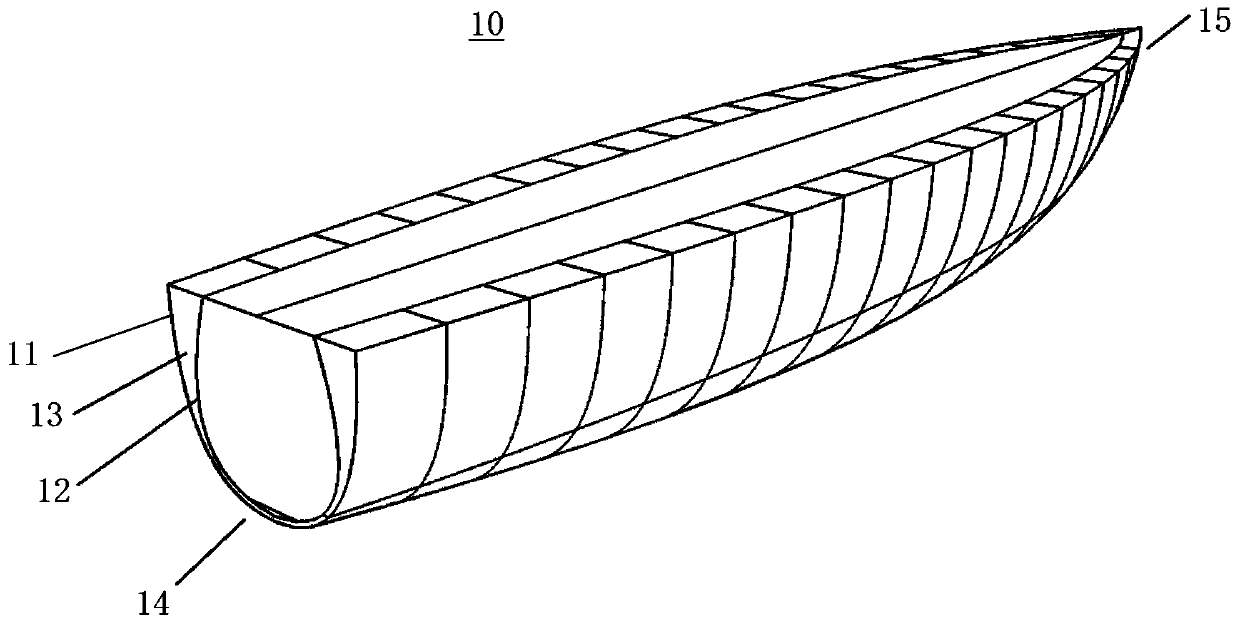
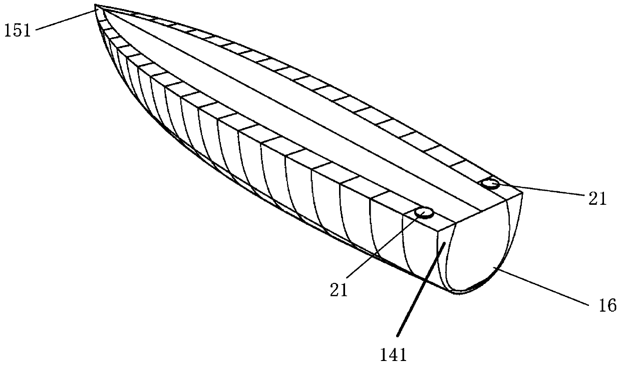
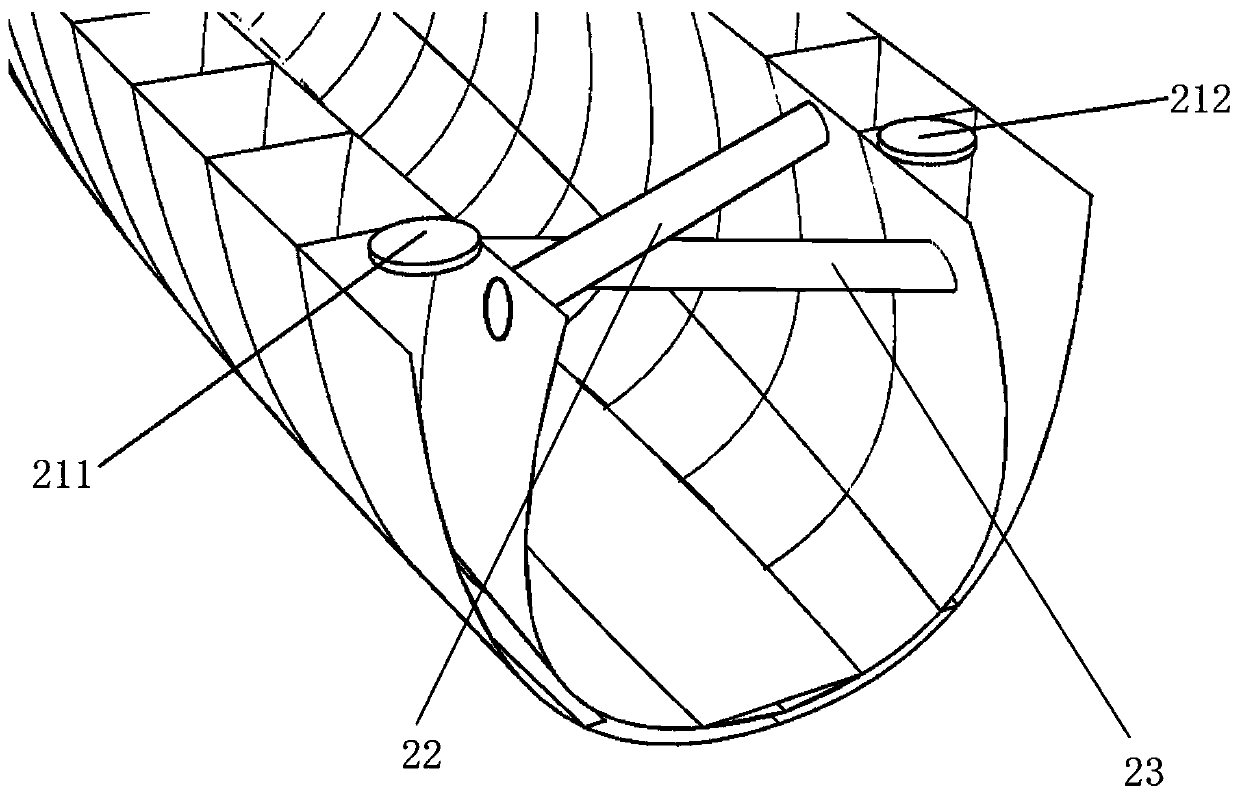
[0030] Such as Figure 1-7 Shown is a water surface floating body rolling propulsion system utilizing wave energy in a preferred embodiment of the present invention, including a hull structure 10 and a pneumatic work device 30, and the air pressure work device 30 includes an air booster 31, an air motor 32 and a propeller 34.

[0031] The hull structure 10 includes an outer shell 11 and an inner shell 12. A plurality of U-shaped cavities 13 are continuously arranged between the outer shell 11 and the inner shell 12 along the ship's length direction. Between adjacent U-shaped cavities 13 separated by bulkheads. The U-shaped cavity 13 includes a first side portion 131 , a second side portion 132 and a bottom 133 , assum...


PUM


Abstract

The invention relates to a water surface floating body rolling propelling system using wave energy. The propelling system comprises a hull structure and an air pressure working device, the air pressure working device comprises an air booster, a pneumatic motor and a propeller, the hull structure comprises an outer hull and an inner hull, a plurality of U-shaped cavities are formed between the outer hull and the inner hull along the length direction of a ship and comprise first sides, second sides and bottoms, the bottoms are filled with liquid, a first side air box and a second side air box ofthe U-shaped cavity of one end are communicated with the outside through a first one-way valve, a first side air box and a second side air box of the U-shaped cavity of the other end are communicatedwith the air booster, the first side of each U-shaped cavity is communicated with the second side of the adjacent U-shaped cavity, and the second side of each U-shaped cavity is communicated with thefirst side of the adjacent U-shaped cavity. According to the propelling system, ship rolling caused by waves serves as course power, adverse effects caused by rolling are changed into navigation power, and ship rolling kinetic energy is transformed into propelling power in a multi-stage pneumatic mode of transverse fluid oscillation.

Description

technical field [0001] The invention relates to the technical field of ship facilities, in particular to a rolling propulsion system of a water surface floating body utilizing wave energy at sea. Background technique [0002] Since the current power output of green energy such as wave energy is relatively limited, and the speed of floating bodies on the water surface is low, power devices using wave energy are mainly suitable for unmanned offshore platforms. After these unmanned surface floating bodies are equipped with advanced control systems, sensor systems, and communication systems, they can replace people in some dangerous, difficult, and repetitive and boring sea work that consumes energy. With the development of unmanned surface floating bodies in the direction of multi-type missions in the future, the requirements for their endurance (single voyage distance) are also getting higher and higher. However, due to trade-offs with speed, seakeeping, payload and power, et...

Claims


Application Information

Patent Timeline
Patent Type & Authority Patents(China)
IPC IPC(8): B63H19/02B63B1/04
CPCB63B1/04B63H19/02Y02T70/5236
Inventor 徐青杨萌范慧丽龚俊斌王玉成
Owner CHINA SHIP DEV & DESIGN CENT
Learn More