Magnetic-conductive guiding structure of Hall ion source

A Hall ion source and magnetic conductivity technology, applied in the field of ion source, can solve the problems of increasing the cost of electricity, increasing the cost of equipment purchase and installation, increasing the production cost of enterprises, etc., and achieves the effects of avoiding interference, simple structure and low production cost.

Pending Publication Date: 2018-11-02
DONGGUAN CHANGYI PHOTOELECTRIC CO LTD
View PDF3 Cites 0 Cited by
  • Summary
  • Abstract
  • Description
  • Claims
  • Application Information

AI Technical Summary

Problems solved by technology

[0004] However, the replacement of traditional permanent magnets by electromagnets not only increases the purchase and installation costs of equipment, but also increases the power costs during use, which will greatly increase the production costs of enterprises

Method used


Image

  • Magnetic-conductive guiding structure of Hall ion source
  • Magnetic-conductive guiding structure of Hall ion source
  • Magnetic-conductive guiding structure of Hall ion source

Examples


Embodiment Construction

[0022] In order to make the object, technical solution and advantages of the present invention clearer, the present invention will be further described in detail below in conjunction with the accompanying drawings.

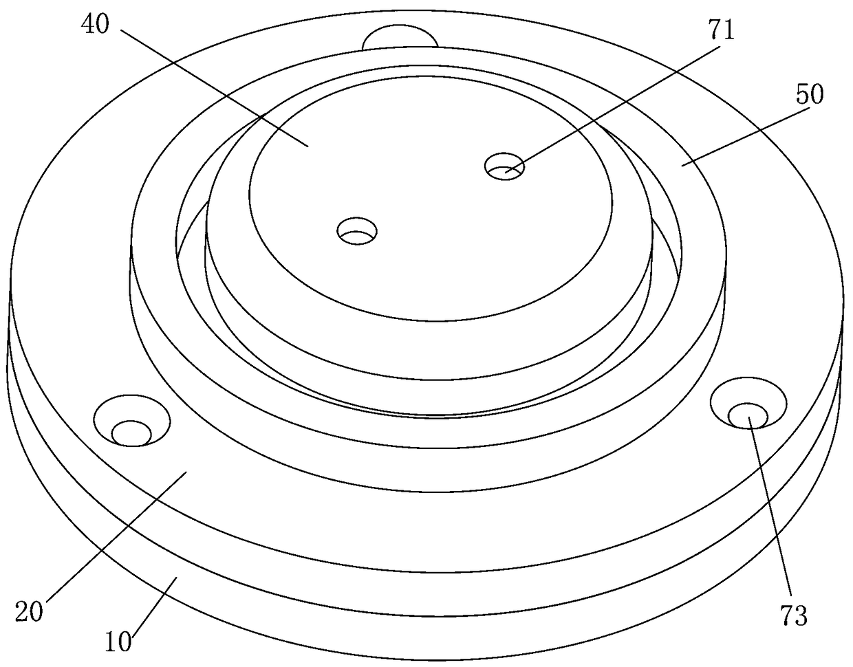
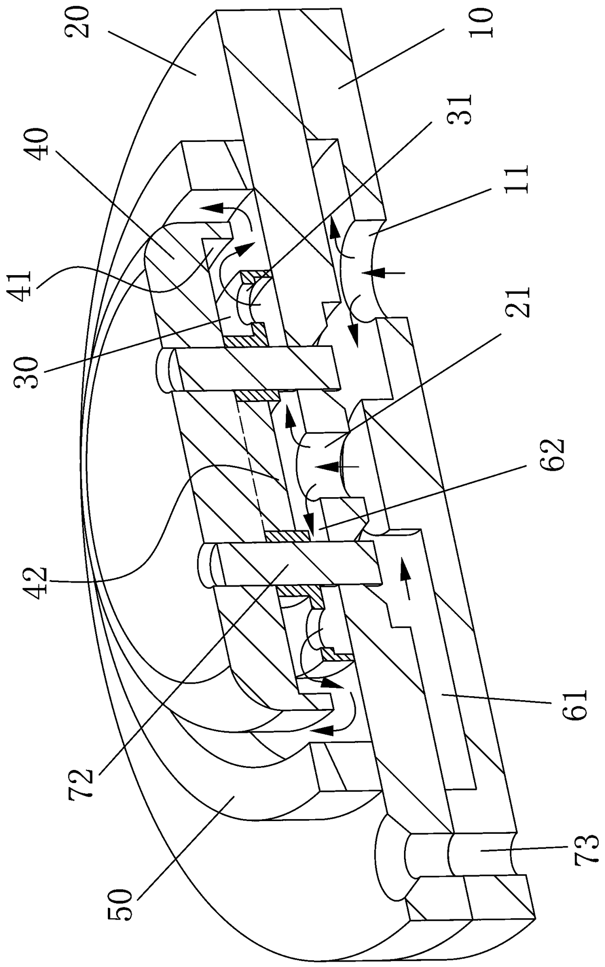
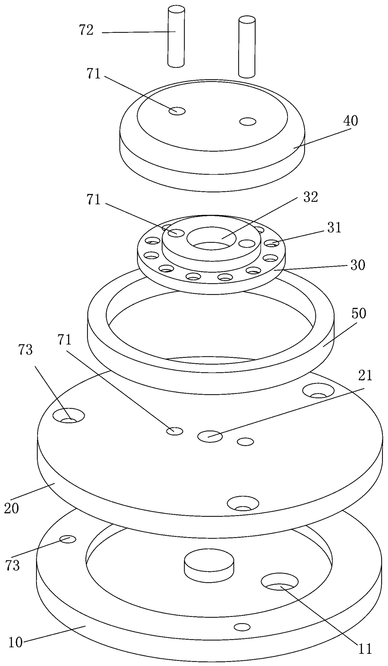
[0023] Such as Figure 1-3 As shown, the embodiment provided by the present invention is a magnetic conduction and current conduction structure of a Hall ion source, which includes an inlet insulating bowl 10, an air passing magnetic disk 20, and an air outlet magnetic conducting bowl 30 arranged in sequence from bottom to top. A lower chamber 61 is provided between the gas-insulating bowl 10 and the air-conducting disk 20 , and an upper chamber 62 is provided between the air-conducting disk 20 and the air-conducting magnetic bowl 30 .

[0024] The intake insulation bowl 10 is provided with an air inlet 11 communicating with the lower chamber 61, the air-conducting magnetic disk 20 is provided with an air-passing hole 21 communicating with the lower chamber 61 and...


PUM


Abstract

The invention provides a magnetic-conductive guiding structure of a Hall ion source, comprising an air inlet insulating bowl, an air venting magnetic-conductive disk and an air outlet magnetic-conductive bowl arranged in order from bottom to top, wherein a lower chamber is disposed between the air inlet insulating bowl and the air venting magnetic-conductive disk, and an upper chamber is disposedbetween the air venting magnetic-conductive disk and the air outlet magnetic-conductive bowl; the air inlet insulating bowl is provided with an air inlet hole communicated with the lower chamber, theair venting magnetic-conductive disk is provided with an air venting hole communicating the upper and lower chambers, and the air outlet magnetic-conductive bowl is provided with an air outlet hole communicated with the upper chamber; the air enters the lower chamber from the air inlet hole, enters the upper chamber through the air venting hole, and finally exits from the air outlet hole. In the invention, an upper chamber is disposed between the air venting magnetic-conductive disk and the air outlet magnetic-conductive bowl, so that the magnetic sensing line is partially restrained within the upper chamber to increasing the magnetic susceptibility of the upper chamber, thereby increasing the magnetic field strength of the upper chamber. The invention is simple in structure and low in production cost.

Description

technical field [0001] The invention relates to the technical field of ion sources, in particular to a magnetic and current-conducting structure of a Hall ion source. Background technique [0002] The ion source is a device that ionizes neutral atoms or molecules and draws an ion beam from it. The Hall ion source ionizes the gas filled in the vacuum chamber by using the emitted electrons under the interaction of the electric field and the magnetic field in a vacuum environment, and emits ions under the action of the electric field and the magnetic field. [0003] The stronger the magnetic field, the longer the trajectory of the electrons, the higher the efficiency of ionizing the process gas, and the larger the resulting ion beam, and vice versa. For example, a Hall ion source disclosed in Chinese patent CN206271656U uses electromagnets instead of traditional permanent magnets, and increases the magnitude of the current flowing through the electromagnets, thereby increasing...

Claims


Application Information

Patent Timeline
Patent Type & Authority Applications(China)
IPC IPC(8): H01J27/02
CPCH01J27/02
Inventor 李雪高
Owner DONGGUAN CHANGYI PHOTOELECTRIC CO LTD
Why Eureka
Try Eureka