High-intensity motor rotor for model airplane

A technology for model airplanes and motor rotors, applied in the direction of electromechanical devices, electrical components, electric components, etc., can solve problems such as affecting flight quality, rising processing costs, and damage to aircraft, so as to improve the ability of anti-deformation and fracture resistance and improve processing Efficiency and assembly efficiency, the effect of low manufacturing cost

Pending Publication Date: 2018-11-02
深圳市三碧精密技术有限公司
View PDF0 Cites 0 Cited by
  • Summary
  • Abstract
  • Description
  • Claims
  • Application Information

AI Technical Summary

Problems solved by technology

[0006] 1) A flat position 8 needs to be made on the rotating shaft 4. When the shaft is pressed into the shaft hole 25, the flat position 8 on the rotating shaft 4 needs to be aligned with the screw hole of the machine meter and then pressed in, adding that the rotating shaft 4 enters the shaft Difficulty in hole 25
[0007] 2) Due to the small size of the head cover 2, when processing the machine screw holes (that is, drilling and tapping), due to the limitation of the operating space, the difficulty is greatly increased, resulting in a substantial increase in processing costs
[0008] 3) After the rotating shaft 4 is pressed into the shaft hole 25, it is necessary to apply glue on the machine screw 7, and then tighten the machine screw 7 in the machine screw hole, resulting in increased assembly hours
[0009] 4) Since the model airplane is an aircraft, it often falls down or collides wit

Method used


Image

  • High-intensity motor rotor for model airplane
  • High-intensity motor rotor for model airplane
  • High-intensity motor rotor for model airplane

Examples


Embodiment Construction

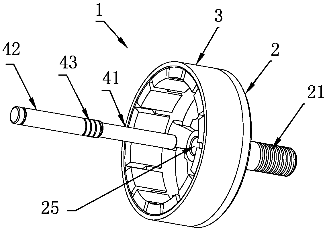
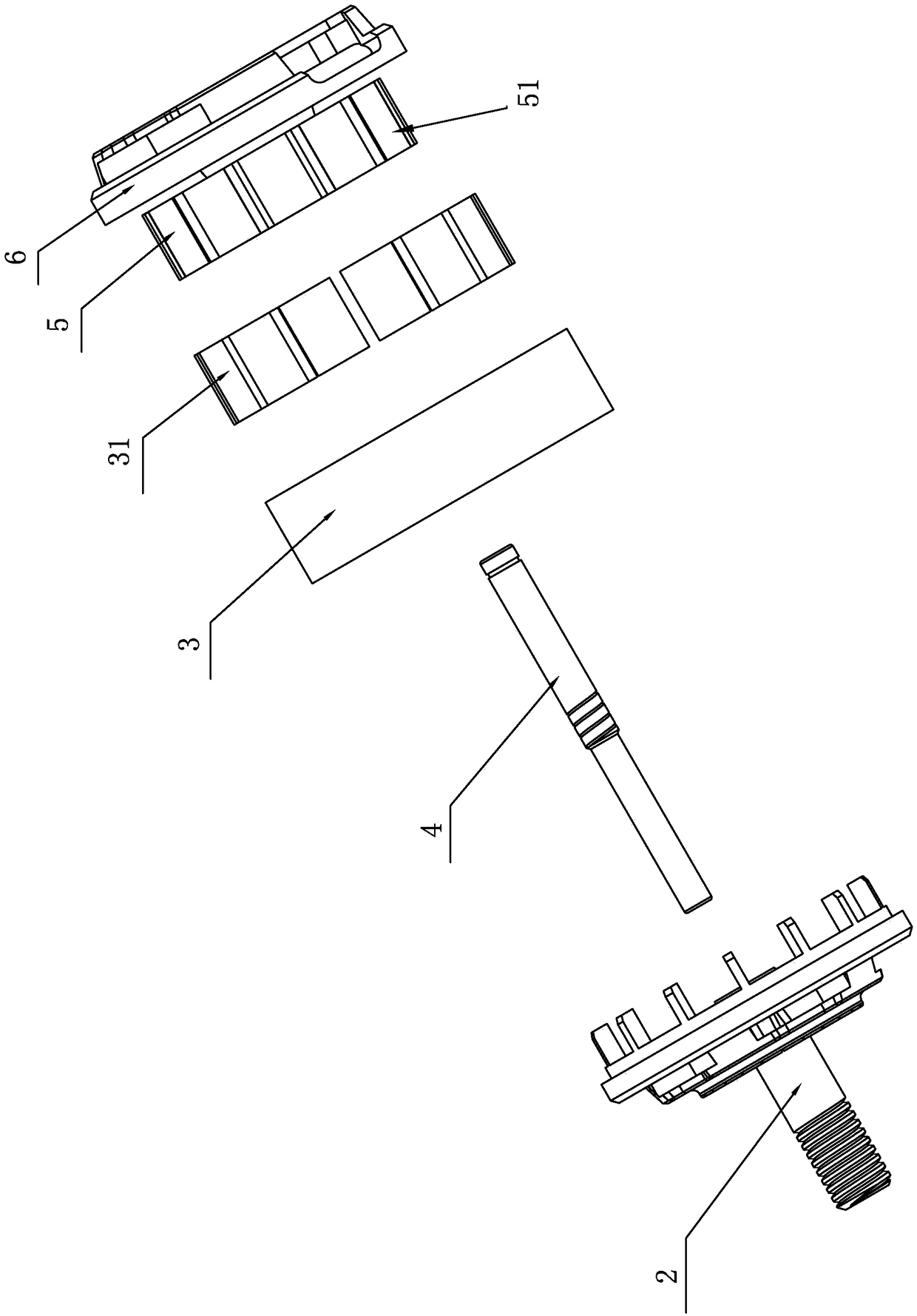
[0032] like image 3 , 5 As shown, the motor 100 that adopts the high-strength motor rotor assembly of the present invention and is used for model aircraft is composed of a rotor 1, a rotating shaft 4, a stator 5 and a bottom cover 6. The rotor 1 is composed of a head cover 2 and a casing 3, and in the casing 3 Several magnets 31 are installed, coils 51 are wound on the stator 5 , and the rotating shaft 4 is connected between the rotor 1 and the stator 5 .

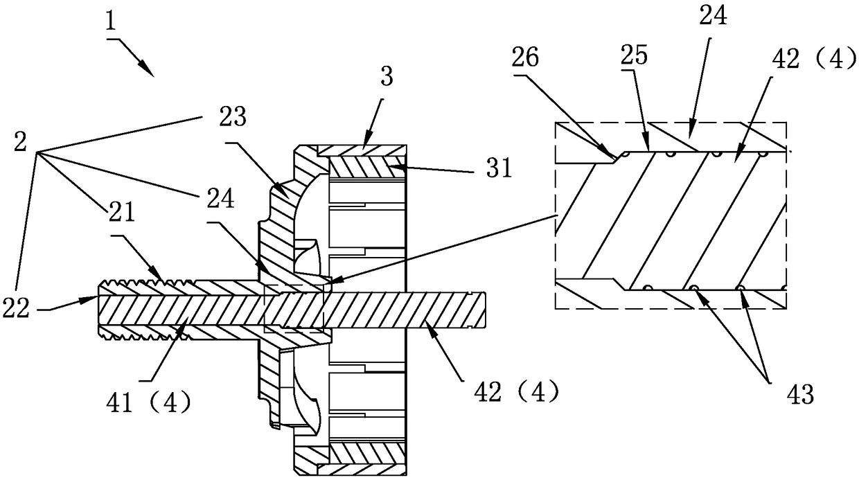
[0033] The present invention mainly aims at the improvement of the connection structure between the head cover 2 of the motor rotor 1 and the rotating shaft 4 of the motor 100 in the prior art, and the beneficial effect is to simplify the connection structure, reduce the manufacturing cost, improve the resistance of the rotor 1 to falling and Anti-collision ability and improve rotor 1 axisymmetric mass distribution.

[0034] The present invention will be described in detail below in conjunction with the accompanying draw...


PUM


Abstract

The invention relates to a high-intensity motor rotor for a model airplane, which is low in manufacturing cost, has collision resistance and is uniform in mass distribution. The high-intensity motor rotor for the model airplane comprises a head cover and a rotating shaft fixedly connected inside a shaft hole on the head cover; a connection screw of the head cover is provided with a hollow passagecoaxially formed with the shaft hole and communicated with the shaft hole; the outside part of the rotating shaft passes through the shaft hole to be inserted in the hollow passage; a plurality of ring-shaped grooves are formed at intervals on the outer peripheral wall of the rotating shaft; and the rotating shaft is fixedly connected with the shaft hole into one whole body by super glue filled inthe ring-shaped grooves. According to the invention, the rotating shaft in a motor is designed into a long shaft from a short shaft in the prior art and is inserted in the hollow passage in the connection screw, so that deformation resistance and fracture resistance of the connection screw are greatly improved. The rotating shaft is fixedly connected with the head cover by epoxy resin, so that machining and assembling efficiency of the head cover is greatly improved, and rotor mass can be guaranteed to be uniformly distributed in a direction of taking the axis as the symmetry axis so as to obtain high flight quality. The high-intensity motor rotor for the model airplane is simple in structure, low in manufacturing cost and few in assembling working time, and can be widely applied to a model external rotation motor.

Description

technical field [0001] The invention relates to a motor, in particular to a motor rotor used for an outrunning motor on a model competitive aircraft. Background technique [0002] The motors used in model airplanes are externally rotating motors. The stator of the externally rotating motor is fixed on the fuselage of the aircraft. The rotor of the externally rotating motor is fixedly connected with the rotor of the aircraft through a connecting screw. The rotor is sleeved on the stator. The coil is set on the stator, and the magnetic poles are set on the rotor. When the current passes through the coil, the rotor wrapped on the stator rotates and drives the rotor to rotate, thereby making the aircraft fly off the ground. [0003] Generally, an externally rotating motor is composed of a rotor, a stator, and a shaft connected between the rotor and the stator. The rotor is composed of a head cover and a casing. The magnetic poles are fixed in the casing, and the casing is fixed ...

Claims


Application Information

Patent Timeline
IPC IPC(8): H02K7/00
CPCH02K7/003H02K2213/03
Inventor 张文龙
Owner 深圳市三碧精密技术有限公司
Why Eureka
Try Eureka