Magnetic assembly device for stator and rotor of permanent magnet motor and application method of magnetic assembly device

A technology for permanent magnet motors and rotors, applied in electromechanical devices, manufacturing motor generators, centering/balancing rotors, etc., can solve the problems of inapplicable assembly of large permanent magnet motors, achieve uniform air gaps, and avoid parts damage, simple effects

Pending Publication Date: 2018-11-02
青岛海西电气有限公司
View PDF0 Cites 2 Cited by
  • Summary
  • Abstract
  • Description
  • Claims
  • Application Information

AI Technical Summary

Problems solved by technology

[0004] At present, most manufacturers adopt the process plan of vertical installation to assemble large permanent magnet motors, but this process plan cannot be applied to the assembly of large permanent magnet motors with bearing pad structure

Method used


Image

  • Magnetic assembly device for stator and rotor of permanent magnet motor and application method of magnetic assembly device
  • Magnetic assembly device for stator and rotor of permanent magnet motor and application method of magnetic assembly device
  • Magnetic assembly device for stator and rotor of permanent magnet motor and application method of magnetic assembly device

Examples


Embodiment 1

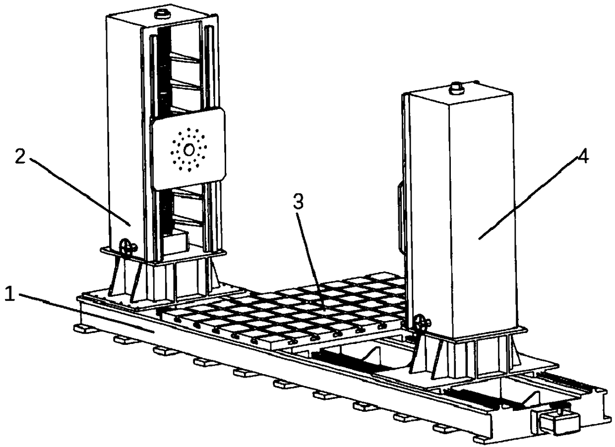
[0092] Such as figure 1 As shown: this embodiment discloses a permanent magnet motor stator and rotor magnetic assembly device, including: a device base 1 located in the motor assembly area, a fixed end gantry support 2, a mobile end gantry support 4, a movable stator Pallet 3, non-drive end extension shaft tooling 5 and drive end conversion shaft tooling 6.

[0093] Wherein, the device base 1 includes a first end and a second end.

[0094] The fixed-end gantry bracket 2 is fixedly arranged at the first end.

[0095] It should be noted that the fixed-end gantry bracket 2 described here is fixed to the first end of the device base 1 by fixing bolts.

[0096] The gantry bracket 4 at the moving end is arranged at the second end, and can move controllably along the length direction of the device base 1 .

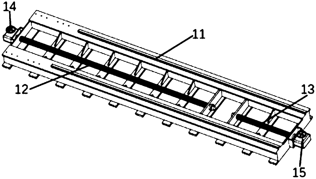
[0097] In detail, the mobile end gantry bracket 4 described here is connected to the second end of the device base 1 through the first linear guide rail group 11 and the seco...

Embodiment 2

[0164] This embodiment discloses a permanent magnet motor stator and rotor magnetic assembly device, which is used to realize the permanent magnet motor stator and rotor assembly.

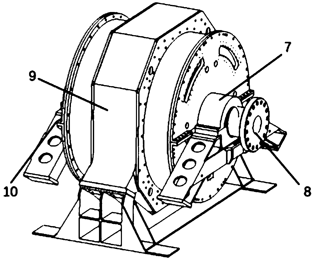
[0165] Specifically, the permanent magnet motor stator and rotor magnetic assembly device disclosed in this embodiment includes: a device base 1, a gantry support 2 at a fixed end, a movable stator tray 3, a gantry support 4 at a moving end, and an extended shaft tooling at a non-driving end 5. Drive end conversion shaft tooling 6, please refer to figure 1 and Figure 8 . A large permanent magnet motor is composed of a bearing shell structure driving end cover assembly 7, a rotor 8, a stator 9, and a bearing shell structure non-driving end cover assembly 10, please refer to figure 2 . The device base 1 is placed on the motor assembly site, and the fixed-end gantry bracket 2 is installed on the first end of the device base 1 . The movable stator tray 3 is connected to the top of the device base...


PUM


Abstract

The invention relates to a magnetic assembly device for a stator and a rotor of a permanent magnet motor and an application method of the magnetic assembly device. The assembly device comprises a device base located in a motor assembly area, a fixed end gantry bracket, a movable end gantry bracket, a movable stator tray, a non-driven-end extended shaft tool and a driven-end conversion shaft tool,wherein the device base comprises a first end and a second end; the fixed end gantry bracket is fixedly arranged at the first end; the movable end gantry bracket is arranged at the second end and canmove in a controllable manner along the length direction of the device base; and the movable stator tray is located on the device base between the fixed end gantry bracket and the movable end gantry bracket and can move in a controllable manner along the length direction of the device base. According to the assembly device and the application method thereof provided by the invention, magnetic assembly of the stator and the rotor of the large permanent magnet motor with a bearing structure can be achieved on the premise of ensuring safety production and qualified product quality.

Description

technical field [0001] The invention belongs to the technical field of assembly of permanent magnet motors, and in particular relates to a device for magnetic assembly of a stator and a rotor of a permanent magnet motor and an application method thereof. Background technique [0002] As a high-efficiency and energy-saving motor, the permanent magnet motor has the advantages of small size, light weight, less loss, and high efficiency. With the development of high-energy permanent magnets, permanent magnet motors have been widely used in various fields of aviation, aerospace, national defense, equipment manufacturing, industrial and agricultural production, and daily life. [0003] The development of large-scale permanent magnet motors is one of the main directions of motor development at present. Since the current technology cannot realize the magnetization of the permanent magnets after the stator and rotor are combined; This is one of the difficulties in the assembly and m...

Claims


Application Information

Patent Timeline
IPC IPC(8): H02K15/16
CPCH02K15/165
Inventor 郑海龙苏浩林博文金晓宇蒋青璋阚立晨赵志强
Owner 青岛海西电气有限公司
Why Eureka
Try Eureka