Filter bag dust collector
A filter bag dust collector and filter bag technology, applied in the direction of dispersed particle filtration, chemical instruments and methods, gas treatment, etc., can solve the problems of uneven distribution of smoke on the surface of the filter bag, low dust removal efficiency, etc., and improve the use of filter bags efficiency, improve the dust removal efficiency, and achieve the effect of uniform passage
- Summary
- Abstract
- Description
- Claims
- Application Information
AI Technical Summary
Problems solved by technology
Method used
Image
Examples
Embodiment 1
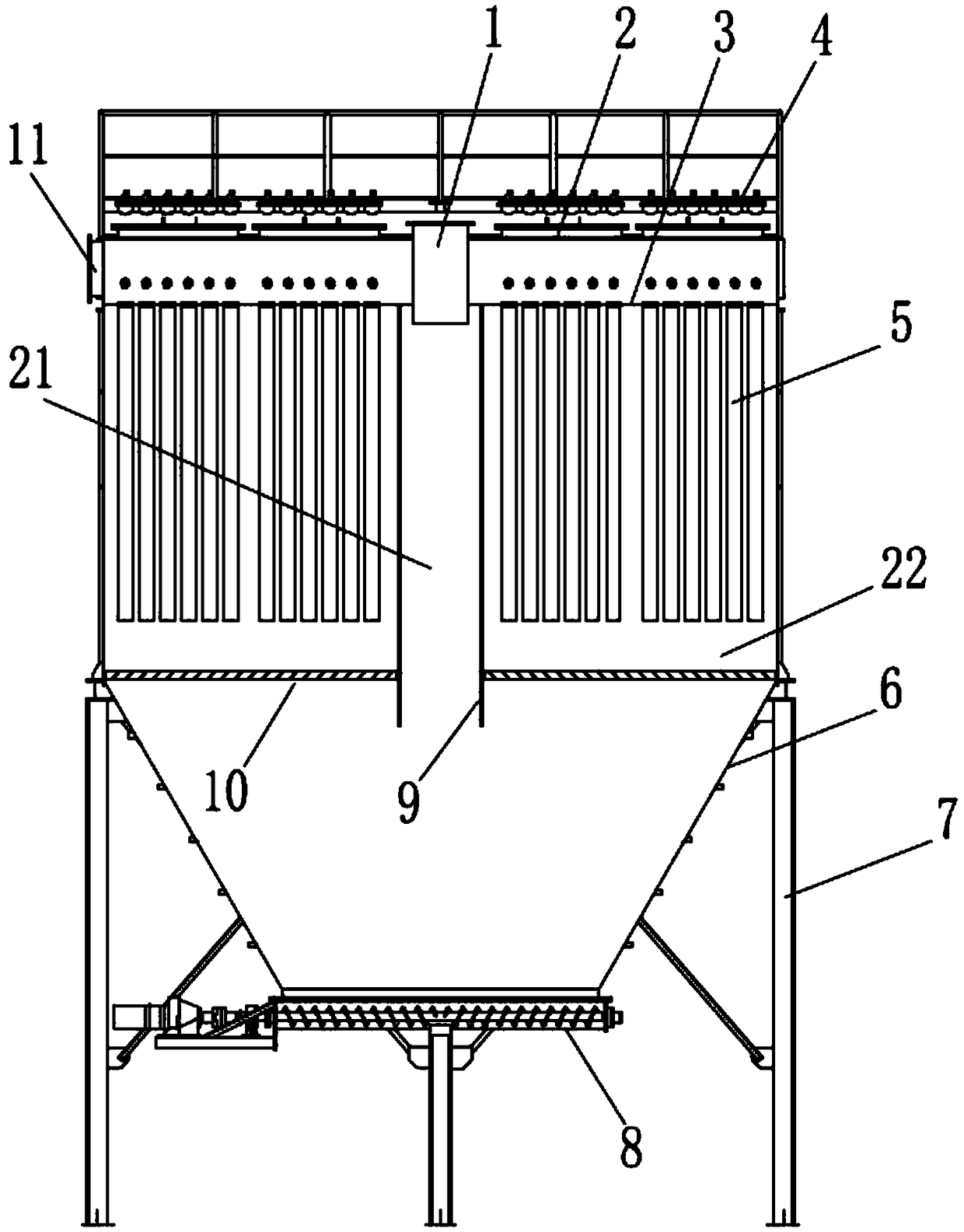
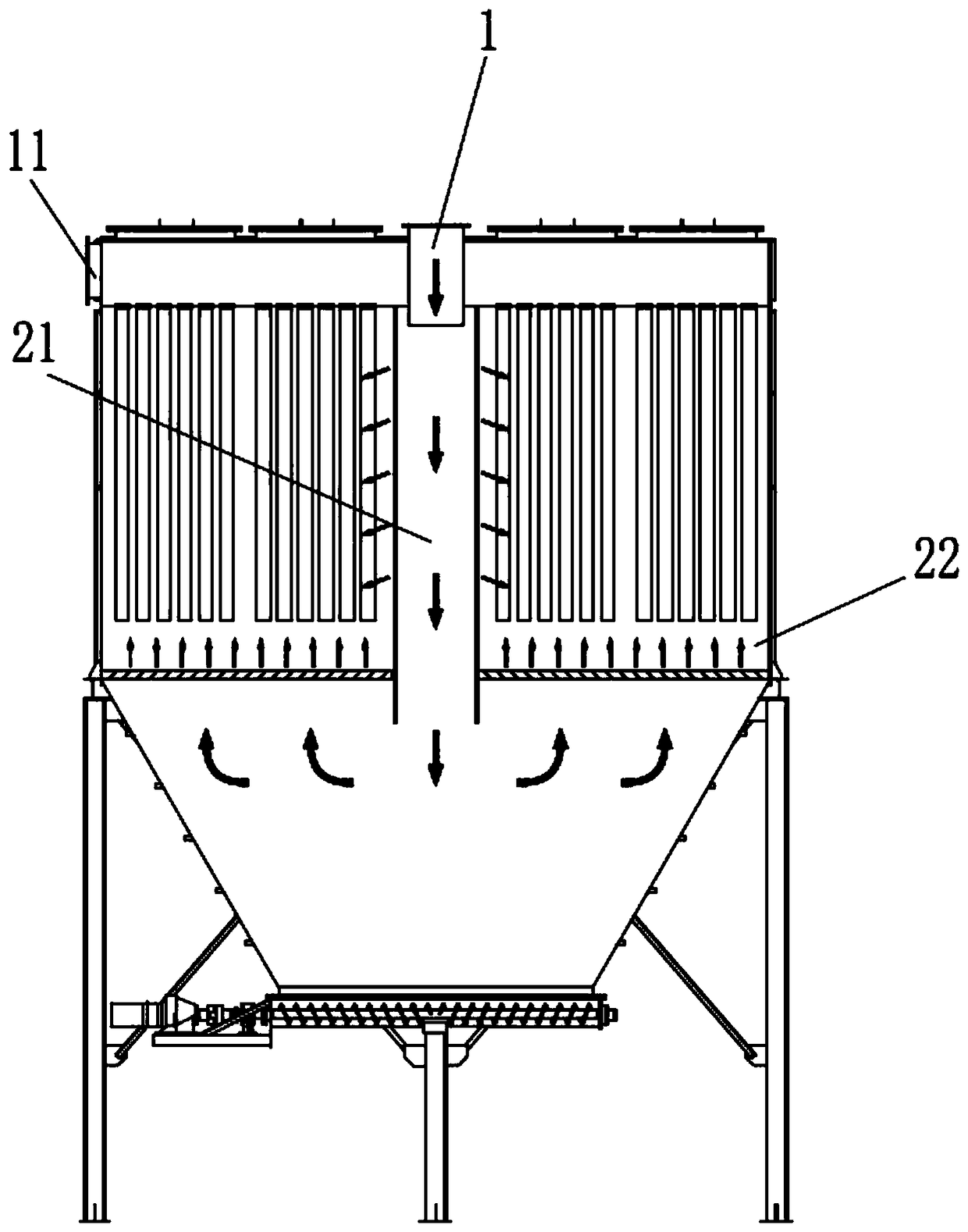
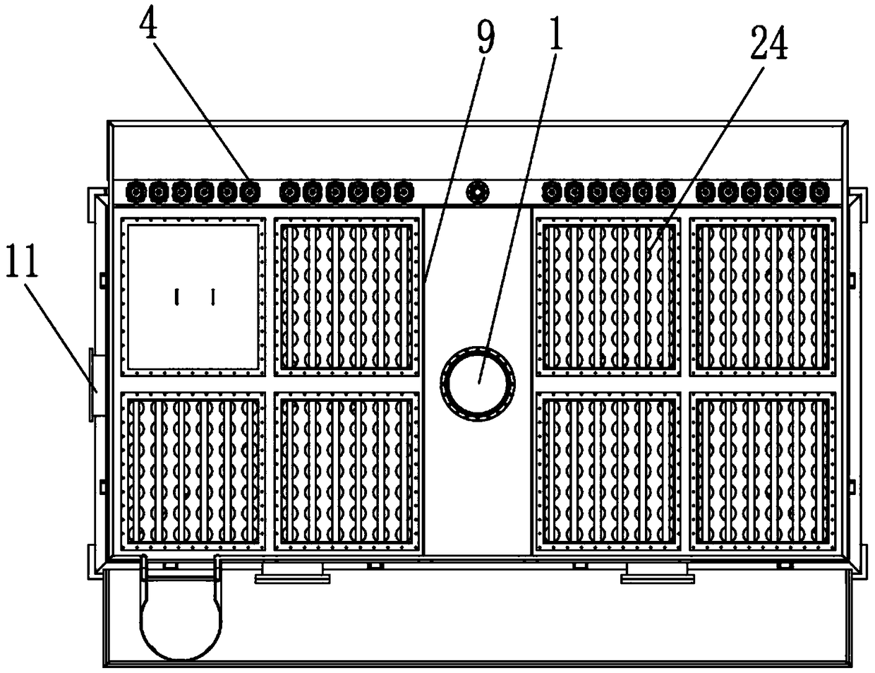
[0042] Such as Figure 1-3 As shown, a filter bag dust collector of this embodiment includes a box shell 2 and a filter plate 3. A filter bag 5 is installed on the filter plate, and the filter bag 5 is installed below the filter plate 5. The filter plate 3 Installed at the upper part of the box shell 2, two vertical flow channel partitions 9 are arranged below the filter plate 3, the surface of the flow channel partitions 9 is smooth and symmetrically distributed, and the two flow channel partitions 9 will The box shell 2 is divided into a smoke flow channel 21 and two dust removal chambers 22, the smoke flow channel 21 is vertically downward, and the dust removal chamber 22 is a closed chamber for dust removal.
[0043] The working principle of the filter bag dust collector of the present invention: reference figure 2 , the flue gas containing fly ash enters the flue gas channel 21 vertically through the inlet assembly 1, a part of the flue gas diffuses to both sides throug...
Embodiment 2
[0045] refer to Figure 4-5 , a filter bag filter of the present embodiment, its structure is basically the same as that of embodiment 1, further:
[0046] In the prior art, the gas flows upward from the bottom of the bag and is parallel to the installation direction of the bag. Only a small amount of gas permeates into the bag from the bottom of the bag, and most of the gas will keep vertically upward until the bottom of the flower plate, and the airflow will be blocked. , and then penetrate the bag.
[0047] There are several long holes 23 in the middle of the flow channel partition 9 of the filter bag dust collector of the present invention. The long holes 23 are to share part of the ash-containing gas directly into the dust removal chamber 22, and the second is to directly allow the gas to face the filter bag 5. Flushing is carried out at one end to increase the forced gas passage to increase penetration and reduce the accumulation of gas to the top of the filter bag 5. T...
Embodiment 3
[0050] It should be pointed out that, in order to realize the uniform passage of flue gas on the surface of the filter bag 5, the difference from Example 2 is that the reference Figure 4 , in this embodiment, the aperture width of the long hole 23 gradually increases from top to bottom. Because the fly ash in the flue gas channel 21 directly enters the middle and lower part of the dust removal chamber 22, and is filtered through the middle and lower surface of the filter bag 5, which is beneficial to improve the dust removal effect, and the gas must pass through the filter bag 5 to enter the upper chamber.
[0051] The filter bag 5 in this embodiment adopts a long cylindrical filter bag 5. Under natural conditions, the load on the upper part of the dust removal filter bag 5 is heavier than the load on the lower part, that is to say, the gas required is less as it goes up. The middle end of the filter bag 5 And the lower end requires more gas to be forced through. Therefore, ...
PUM
 Abstract
Description
Claims
Application Information
 - R&D
- Intellectual Property
- Life Sciences
- Materials
- Tech Scout
- Unparalleled Data Quality
- Higher Quality Content
- 60% Fewer Hallucinations
Browse by: Latest US Patents, China's latest patents, Technical Efficacy Thesaurus, Application Domain, Technology Topic, Popular Technical Reports.
© 2025 PatSnap. All rights reserved.Legal|Privacy policy|Modern Slavery Act Transparency Statement|Sitemap|About US| Contact US: help@patsnap.com


