
Material cutting and cutting plate device for circuit plate processing

A circuit board and cutting board technology is applied in the field of cutting and cutting devices for circuit board processing, which can solve the problems of affecting the cutting and cutting effect of the board, not having vibration buffering and absorption, and the position of the board being easy to move, etc. effect, improve usability, avoid the effect of movement

Pending Publication Date: 2018-11-06
湖北荣宝电子科技有限公司
View PDF10 Cites 11 Cited by
  • Summary
  • Abstract
  • Description
  • Claims
  • Application Information

AI Technical Summary

Problems solved by technology

[0003] The existing cutting and cutting device for circuit board processing does not have the function of cutting and cutting boards of different specifications. It is easy to move, which affects the effect of plate cutting and cutting. At the same time, the existing cutting and cutting devices for circuit board processing do not have the purpose of buffering and absorbing the vibration generated during the cutting and cutting of plates. The vibration is too large. It is easy to cause certain damage to the board itself. At the same time, the existing board cutting device for circuit board processing needs to manually move the board when cutting different positions of the board, which wastes a lot of manpower and is not practical.

Method used


Image

  • Material cutting and cutting plate device for circuit plate processing
  • Material cutting and cutting plate device for circuit plate processing
  • Material cutting and cutting plate device for circuit plate processing

Examples


Embodiment Construction

[0016] The following will clearly and completely describe the technical solutions in the embodiments of the present invention with reference to the accompanying drawings in the embodiments of the present invention. Obviously, the described embodiments are only some, not all, embodiments of the present invention. Based on the embodiments of the present invention, all other embodiments obtained by persons of ordinary skill in the art without making creative efforts belong to the protection scope of the present invention.

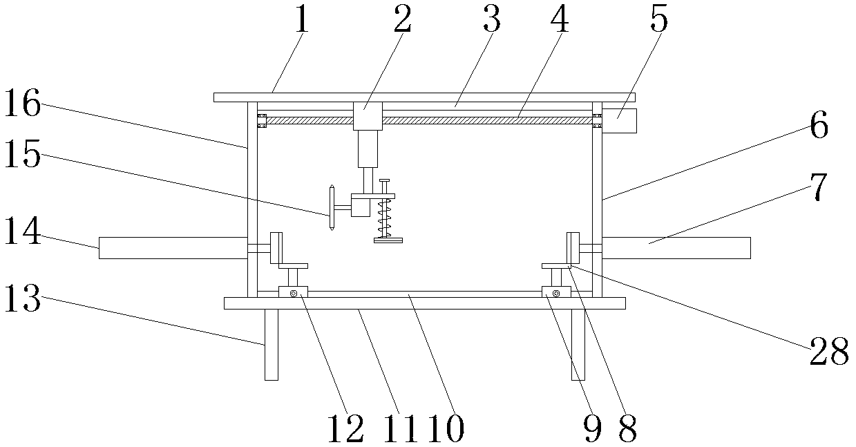
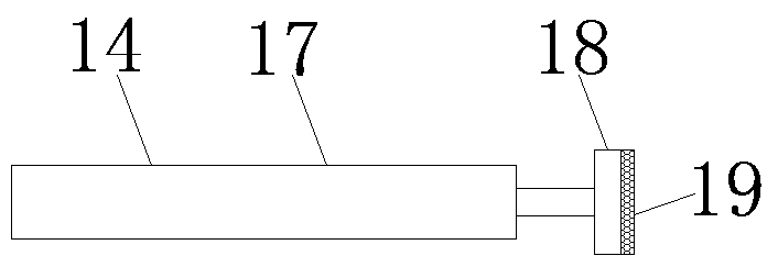
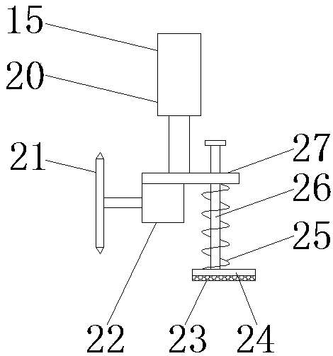
[0017] see Figure 1~3 , in an embodiment of the present invention, a material cutting device for circuit board processing, including a top plate 1, a first slider 2, a first slide rail 3, a screw rod 4, a motor 5, a first support plate 6, a first Fixing device 7, second slide rail 10, base plate 11, first placing device 12, support leg 13, second fixing device 14, cutting device 15, second supporting plate 16 and second placing device 28, described base plate...


PUM


Abstract

The invention discloses a material cutting and cutting plate device for circuit plate processing. The device comprises a first air cylinder, a second air cylinder, a second anti-skid pad, a pressing plate, a cutting blade, a bottom plate and a top plate; the second air cylinder is used for driving a piston rod to extend so as to push the pressing plate to move downwards to be in contact with the top of the plate, so that the purpose of fixing the position of the plate is further achieved; the friction force between the bottom of the pressing plate and the top of the plate is increased by arranging the second anti-skid pad, the effect of fixing the position of the plate is further improved, and the effect of cutting the plate is further guaranteed; the second air cylinder further drives thepiston rod to extend, so that the cutting blade is further pushed to move downwards to be in contact with the top of the plate and a damping spring is extruded; and through the rotation of a cuttingmotor, the cutting blade is driven to rotate so as to cut the plate, so that the purpose of cutting the plate is achieved, and the operation is simple.

Description

technical field [0001] The invention relates to a material cutting and board cutting device, in particular to a material cutting and board cutting device for circuit board processing. Background technique [0002] PCB (Printed Circuit Board), the Chinese name is printed circuit board, also known as printed circuit board, is an important electronic component, a support for electronic components, and a carrier for electrical connections of electronic components. Because it is made by electronic printing, it is called "printed" circuit board. After electronic equipment uses printed boards, due to the consistency of similar printed boards, manual wiring errors are avoided, and electronic components can be realized. Automatic device insertion or placement, automatic soldering, and automatic detection ensure the quality of electronic equipment, improve labor productivity, reduce costs, and facilitate maintenance; [0003] The existing cutting and cutting device for circuit board ...

Claims


Application Information

Patent Timeline
Patent Type & Authority Applications(China)
IPC IPC(8): B26D1/18B26D5/04B26D5/08B26D7/02B26D7/26F16F15/04
CPCF16F15/04B26D1/18B26D5/04B26D5/08B26D7/02B26D7/2635F16F2238/026
Inventor 曾凡伍呼宝宝
Owner 湖北荣宝电子科技有限公司
Learn More