
Electrified sintering die

A mold, energization technology, applied in the direction of molds, manufacturing tools, ceramic forming cores, etc., can solve the problems of cold welding, inconsistent temperature distribution sintering, sample crushing, etc., to achieve the effect of improving service life

Active Publication Date: 2018-11-06
SHANGHAI INST OF CERAMIC CHEM & TECH CHINESE ACAD OF SCI
View PDF5 Cites 5 Cited by
  • Summary
  • Abstract
  • Description
  • Claims
  • Application Information

AI Technical Summary

Problems solved by technology

[0004] The use of such an electrified sintering mold has the following problems: (1) During electrified sintering, for samples with good material conductivity, the current mainly passes through the material of the sample except for a part through the mold, and the heating is mainly through the mold. and material self-heating; for samples with poor conductivity or non-conductive materials, the current mainly passes through the mold, and the heating is realized through the heating of the mold. These heating methods lead to uneven temperature distribution and temperature distribution. Inhomogeneity will lead to inconsistent sintering, which will affect the uniformity and performance of the material; (2) Due to the low hardness of the current graphite mold, it is easy to wear the inner cavity wall of the mold when the sample exits from the mold, while the alloy mold has a higher hardness. , but the indenter may be slightly deformed after high-temperature and high-pressure sintering, which may easily cause the indenter to scratch the inner wall of the alloy mold or cause cold welding when the sample is returned, which may damage the mold
At the same time, some samples are tightly squeezed into the mold after cooling down from high temperature. If they are forced out, the graphite mold is easy to crack or the sample is often crushed.

Method used


Image

  • Electrified sintering die
  • Electrified sintering die
  • Electrified sintering die

Examples


Embodiment Construction

[0038] The present invention will be further described below in conjunction with the accompanying drawings and specific embodiments. It should be understood that the following embodiments are only for illustrating the present invention, rather than limiting the present invention.

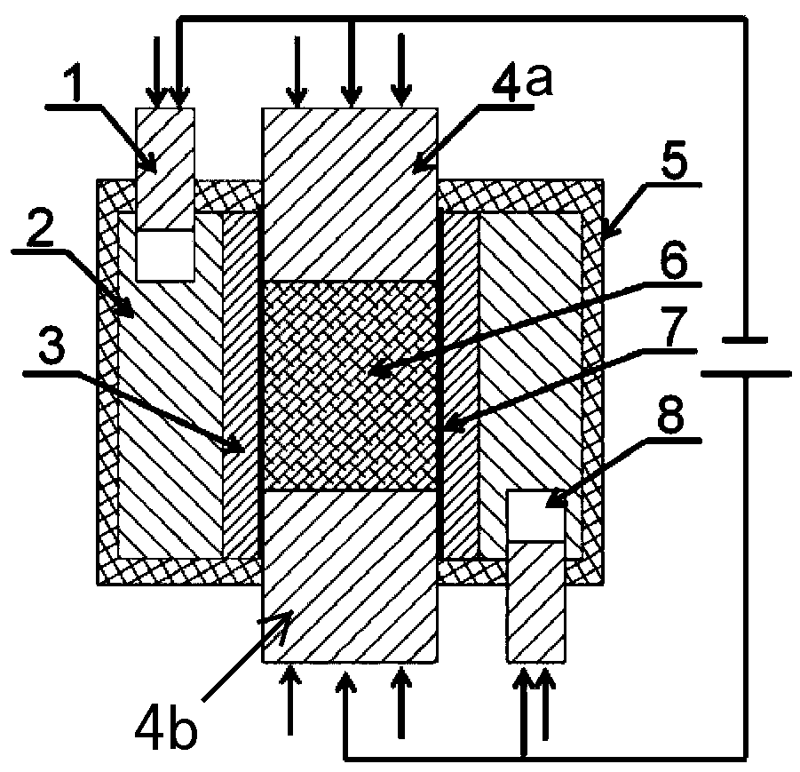
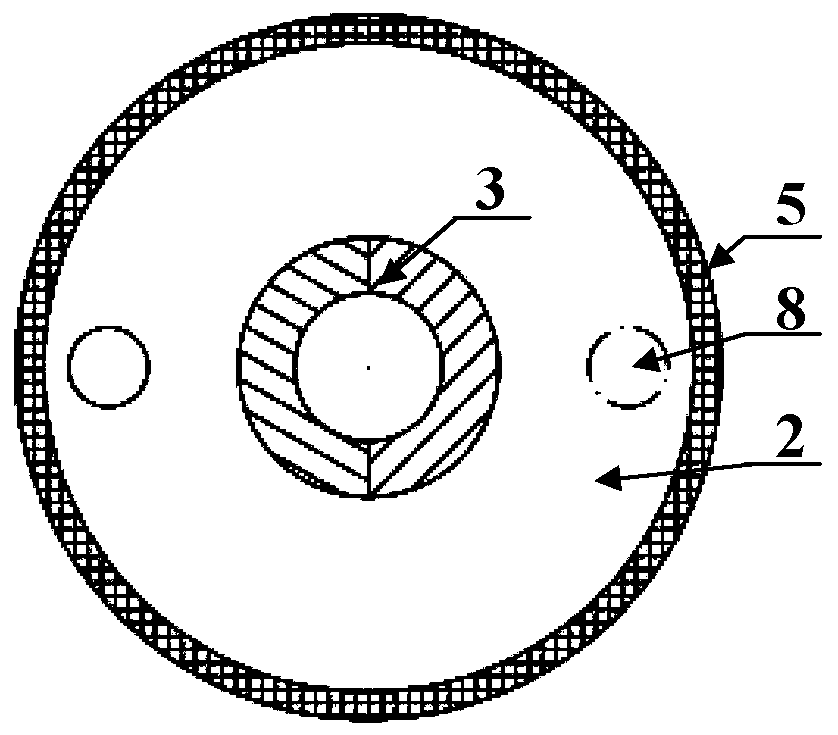
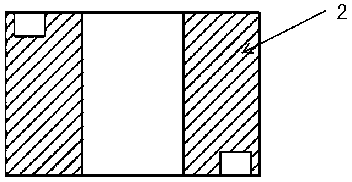
[0039] Aiming at the problems of uneven temperature distribution of the energized sintering mold and easy damage of the mold and samples in the prior art, the present invention provides an energized sintering mold capable of improving the uniformity of the sintering temperature field and thereby improving the sintering uniformity of the sample. The mold includes: an inner loose block forming die and an outer mold cover arranged from the inside to the outside; and an upper pressure head and a lower pressure head arranged in the inner loose block forming die; a counterbore is provided on the outer mold cover ; There is a shunt guide body in the counterbore; a mold release agent is coated on the inner w...


PUM


Abstract

The invention provides an electrified sintering die which comprises an internal movable block forming die and an outer die sleeve arranged from inside to outside and further comprises an upper pressure head and a lower pressure head arranged in the internal movable block forming die, wherein a counterbore hole is formed in the outer die sleeve; a shunting flow deflector is arranged in the counterbore hole; and the inner wall of the outer die sleeve or the outer wall of the internal movable block forming die is coated with a release agent. The electrified sintering die can improve the uniformity of a sintering temperature field and reduces the demoulding difficulty of a sintered sample to improve the sintering uniformity of the sample and the integrity of the sintered sample.

Description

technical field [0001] The invention belongs to the modification technology of a sintering mold, and relates to a sintering mold, in particular to an electric sintering mold. Background technique [0002] In the field of special ceramics and thermoelectric bulk materials, it is often necessary to rapidly sinter samples with fine grains at high temperature. Compared with the sintering method of external heating, electric sintering is an effective sintering method that can achieve high temperature and rapid sintering. [0003] The molds for these high-temperature sintered samples often use graphite molds or high-temperature-resistant alloy molds with high melting points and low expansion coefficients. The main body of its typical structure is cylindrical, and the powder sample is placed in a circular or other shaped cavity. During sintering, pressure heads are placed at both ends of the powder sample to apply pressure. After high-temperature sintering, the pressure head is ej...

Claims


Application Information

Patent Timeline
IPC IPC(8): B28B7/02B28B7/30B28B7/38B22F3/14
CPCB22F3/003B22F3/14B28B7/02B28B7/30B28B7/384
Inventor 夏绪贵陈立东廖锦城顾明柏胜强吴汀吴洁华李小亚
Owner SHANGHAI INST OF CERAMIC CHEM & TECH CHINESE ACAD OF SCI
Learn More