Compression system based on gear occlusion transmission

A compression system and gear technology, applied in presses, recycling technology, plastic recycling, etc., can solve the problem of high cost, and achieve the effects of convenient assembly and disassembly, ingenious design and simple structure

Inactive Publication Date: 2018-11-06
MIANYANG FEIYUAN TECH CO LTD
View PDF0 Cites 0 Cited by
  • Summary
  • Abstract
  • Description
  • Claims
  • Application Information

AI Technical Summary

Problems solved by technology

[0003] The technical problem to be solved by the present invention is to provide a compression system based on gear meshing transmission, which solves the problem of corresponding to some small recycling stations, the cost of purchasing large-scale crushing equipment is too high, and the use of matching products is required in the field of small-batch crushing and crushing

Method used


Image

  • Compression system based on gear occlusion transmission

Examples


Embodiment 1

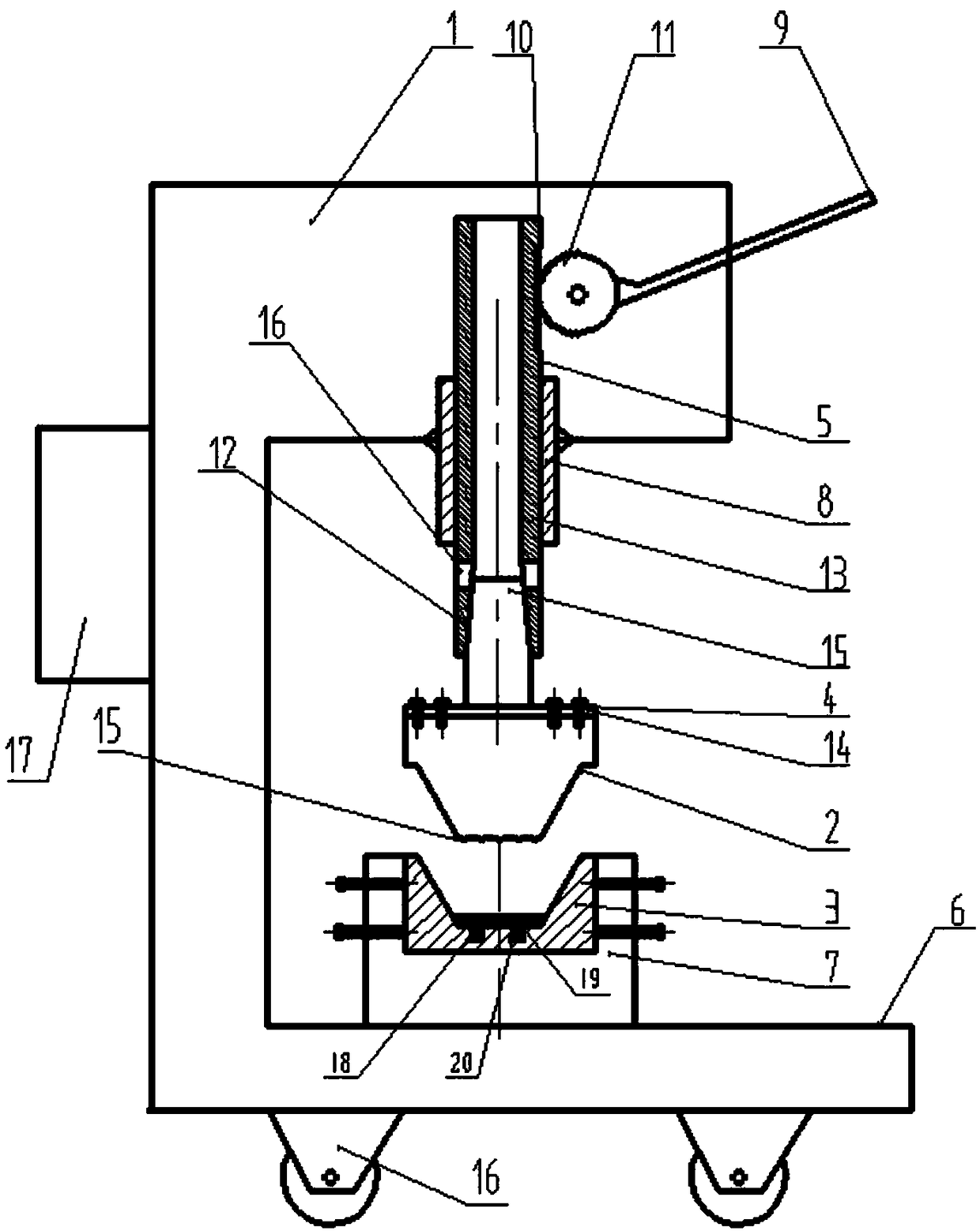
[0016] Such as figure 1 A compression system based on gear meshing transmission is shown, including a waste compression support frame 1, a waste compression upper mold 2, a waste compression lower mold 3, an upper mold connector 4, a waste compression lifting assembly 5 and a gear pressing rod assembly 9, The waste material compression support frame 1 is provided with an operation table 6, and the operation table 6 is provided with a lower mold installation bayonet 7, and the waste material compression lower mold 3 is installed in the lower mold installation bayonet 7, and the waste material compression upper mold 3 passes through The upper mold connector 4 is assembled on the waste compression lifting assembly 5, the waste compression lifting assembly 5 is arranged in the lifting slide 8 on the top of the waste compression support frame 1, and the waste compression lifting assembly 5 is provided with lifting rack teeth 10 , the gear press bar assembly 9 is installed on the to...

Embodiment 2

[0021] Such as figure 1 Shown is a compression system based on gear meshing transmission. On the basis of Embodiment 1, the upper mold connector 4 includes a connecting plate 14 and a connecting shaft 15, and one end of the connecting shaft 15 is welded to the connecting plate 14 The other end is conical and installed in the inner conical cylinder 12 of the lifting cylinder 13, and the connecting plate 14 is connected with the upper mold 2 for crimping the scrap by bolts. When needing to change waste material crimping upper mold 2, use wedge to insert in the wedge groove 16 on the lifting cylinder 13 and beat, upper mold connector 4 just can come off. A sliding wheel 16 is provided at the bottom of the waste compression frame 1 to facilitate the movement of the waste compression device, and a push handle frame 17 is provided outside the waste compression frame 1 .


PUM


Abstract

The invention discloses a compression system based on gear occlusion transmission. A lower die mounting bayonet is formed in an operating table; a waste material compression lower die is mounted in the lower die mounting bayonet; a waste material compression upper die is assembled on a waste material compression and lifting assembly through an upper die connecting piece; the waste material compression and lifting assembly is arranged in a lifting sliding cylinder at the top of a waste material compression supporting frame; lifting strip teeth are formed on the waste material compression and lifting assembly; a gear compression bar assembly is mounted at the upper part of the waste material compression supporting frame through a rotating shaft; gear teeth of the gear compression bar assembly are engaged with the lifting strip teeth of the waste material compression and lifting assembly; the waste material compression and lifting assembly comprises a lifting cylinder; an internal cone barrel is arranged at the lower end of the lifting cylinder; a wedge groove is formed in the part, at the upper end of the internal cone barrel, of the lifting cylinder; the waste material compression upper die is of a bulge structure; the waste material compression lower die is of a groove structure; a tip is arranged at the bottom surface of the bulge structure of the waste material compression upper die; and a compressed waste material is popped up through an elastic pressing plate.

Description

technical field [0001] The invention relates to the technical field of environmental protection waste recycling, in particular to a compression system based on gear meshing transmission. Background technique [0002] In the recycling of waste materials, it is often necessary to squeeze and store some thin metal and plastic waste products to reduce the occupied space and facilitate transportation. It corresponds to some small recycling stations. The cost of purchasing large crushing equipment is too high. Small batch crushing and crushing The field requires the use of supporting products. Contents of the invention [0003] The technical problem to be solved by the present invention is to provide a compression system based on gear meshing transmission, which solves the problem of corresponding to some small recycling stations, the cost of purchasing large-scale crushing equipment is too high, and the field of small-batch crushing crushing needs matching products. [0004] T...

Claims


Application Information

Patent Timeline
Patent Type & Authority Applications(China)
IPC IPC(8): B30B9/32B29B17/00
CPCB29B17/0026B30B9/32B30B9/321Y02W30/62
Inventor 李艳芬
Owner MIANYANG FEIYUAN TECH CO LTD
Why Eureka
Try Eureka