Expansion increment deflagration fracturing method

A deflagration and fracturing technology, which is used in earth-moving drilling, production of fluids, wellbore/well components, etc., can solve the problem of limited deflagration and fracturing functions and effects, poor pore connectivity of perforation channels, and limited deflagration and fracturing dosage. and other problems to achieve the effect of improving connectivity, reducing damage and damage, and avoiding damage

Active Publication Date: 2018-11-06
肖毅 +1
View PDF13 Cites 6 Cited by
  • Summary
  • Abstract
  • Description
  • Claims
  • Application Information

AI Technical Summary

Problems solved by technology

[0003] 1. Volume of the perforation channel—the volume of the perforation hole is small; there is a perforation compaction zone formed by the perforation compaction around the perforation channel, and the connectivity between the perforation channel and the primary pores of the reservoir is poor;
[0004] 2. The same liquid is in the wellbore, and the wellbore is not isolated;
[0009] Due to the disadvantages of damage and damage to the wellbore, cables and tubing in deflagration fracturing, the dosage of deflagration fracturing is limited
The problem is that the energy generated by deflagration fracturing and the energy acting on the near-wellbore zone of the reservoir are low, which limits the function and effect of deflagration fracturing

Method used


Image

  • Expansion increment deflagration fracturing method
  • Expansion increment deflagration fracturing method
  • Expansion increment deflagration fracturing method

Examples


Embodiment 1

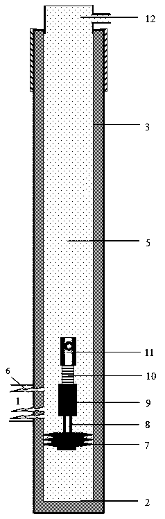
[0046] see figure 1 , a deflagration fracturing method for expansion and increment, comprising the following steps:

[0047] Perforation: perforating in the wellbore 3 where the well section of the target reservoir is located;

[0048] Capacity expansion: improve the connectivity between the perforation channel 6 and the primary pores in the near-wellbore area of ​​the reservoir, and expand the pore volume in the near-wellbore area of ​​the reservoir; the methods for realizing capacity expansion include perforation expansion and plugging expansion; The pore density, pore diameter and pore depth; plugging removal and expansion refers to the recovery and improvement of the connectivity between the perforation tunnel 6 and the primary pores through repeated injection and flowback of the plugging removal fluid into the perforation tunnel 6, increasing the reservoir near the wellbore. The pore volume of the zone; the plugging solution is water-based plugging solution and / or oil-ba...

Embodiment 2

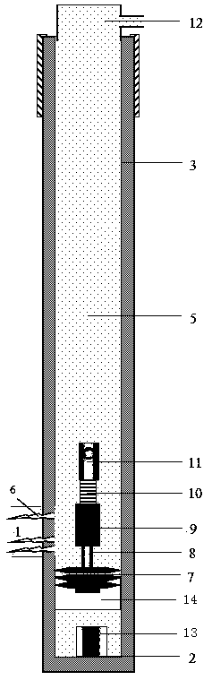
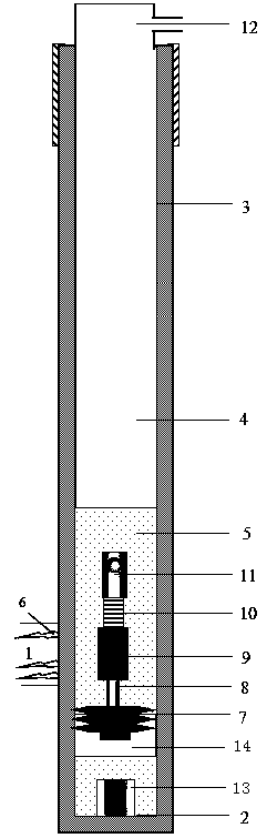
[0056] see figure 2 , on the basis of the above-mentioned basic scheme, after setting the blockage 7, set the gas plug 14 in the wellbore 3 below the blockage 7, the gas plug 14 refers to the gas slug arranged in the wellbore 3 below the blockage 7, the blockage 7 and its lower Adjacent gas plugs 14 jointly form the bottom block; gas plug 14 is a kind of nitrogen, air or carbon dioxide gas; gas plug 14 also can be the mixed gas of nitrogen and air or the mixed gas of carbon dioxide gas and air.

[0057] The setting method of air plug 14 comprises exhaust method or integrated method, wherein:

[0058] The pumping method is: before setting the bottom stop, the liquid in the wellbore 3 is pumped to the surface, so that the liquid in the wellbore 3 drops below the bottom boundary of the perforated well section 1 and above the artificial well bottom, and then the liquid in the wellbore A bottom stop is set above the liquid level in 3, and the sealed air below the bottom stop cons...

Embodiment 3

[0063] 1. Brief introduction of oil production well

[0064] Well number: j06-19, horizon: Y, perforated section: 1615.0-1618.0m, perforation thickness: 3.0m, artificial well bottom: 1769.6m, reservoir casing: φ 内 124.26mm.

[0065] 2. Implementation steps

[0066] 1. The combined bottom stop is used as a pipe / rod column

[0067] Bottom retainer joint pipe string includes bridge plug, well gauge, support joint and tubing. From bottom to top, bridge plug, well gauge and support joint are connected in sequence. Oil pipe and support joint can also be connected between well gauge and support joint. The upper end is connected to the oil pipe.

[0068] The bottom block combined rod column includes a rod pump, a slide rod and a sucker rod, the lower end of the sucker rod is connected with the slide rod, and the lower end of the slide rod is connected with the rod type pump.

[0069] 1.1. Bottom baffle combined as pipe string combination (from bottom to top)

[0070] Bridge plug ...


PUM


Abstract

The invention relates to an expansion increment deflagration fracturing method. The method includes the following steps that perforation is carried out; expansion is carried out; a plug is arranged, specifically, the plug with a blocking function is arranged in the portion, located under the bottom boundary of a perforation well section and above the bottom boundary of a reservoir well section, ofa shaft, the plug blocks and isolates the portion, below the plug, of the shaft and the portion, above the plug, of the shaft, and the plug forms a bottom block; a pressure block is arranged, specifically, a fluid section plug is arranged in the portion, above the bottom block, of the shaft, so that the pressure block with pressurizing and buffering effects is formed; a deflagration fracturing device is arranged, specifically, the deflagration fracturing device connected to the lower end of an oil pipe or a cable is separated from a releasing sub of the oil pipe or the cable, and the deflagration fracturing device independently sits on the upper end face of the bottom block; and the deflagration fracturing device is stimulated and deflagrated, so that expansion increment deflagration fracturing of the reservoir well section is completed. The method can greatly expand the working volume of deflagration fracturing at the near-wellbore region of a reservoir; the limitation of chemical dose for deflagration fracturing is eliminated or reduced, so that the chemical dose for deflagration fracturing is increased; and damage of deflagration fracturing to the shaft or the oil pipe or the cable is lowered or avoided.

Description

technical field [0001] The invention relates to the technical field of exploration and development of mineral resources such as oil, natural gas, coal bed methane, geothermal and in-situ leaching, and in particular provides a deflagration and fracturing method for expansion and increment. Background technique [0002] In order to improve the seepage capacity of the near-wellbore area of ​​the reservoir, deflagration fracturing, also known as high-energy gas fracturing, is widely used in various wells completed with casing perforation. In fact, the operation conditions have the following main characteristics: [0003] 1. Volume of the perforation channel—the volume of the perforation hole is small; there is a perforation compaction zone formed by perforation compaction around the perforation channel, and the connectivity between the perforation channel and the primary pores of the reservoir is poor; [0004] 2. The same liquid is in the wellbore, and the wellbore is not isola...

Claims


Application Information

Patent Timeline
Patent Type & Authority Applications(China)
IPC IPC(8): E21B43/263
CPCE21B43/263
Inventor 肖毅肖肖
Owner 肖毅
Why Eureka
Try Eureka