Crankcase ventilation system and gas engine

A crankcase ventilation and crankcase technology, which is applied to crankcase ventilation, engine components, machines/engines, etc., can solve the problems of inability to effectively control crankcase pressure, deterioration of emissions, and large loss of oil volume, and to ensure normal oil volume. , the effect of reducing pollution

Pending Publication Date: 2018-11-06
湖南省力宇燃气动力有限公司
View PDF0 Cites 2 Cited by
  • Summary
  • Abstract
  • Description
  • Claims
  • Application Information

AI Technical Summary

Problems solved by technology

[0004] The purpose of the present invention is to provide a crankcase ventilation system and a gas engine, so as to alleviate the technical problems that the crankcase ventilation system in the prior art has a large loss of oil, worsened emissions, and can not effectively control the crankcase pressure while filtering gas

Method used


Image

  • Crankcase ventilation system and gas engine
  • Crankcase ventilation system and gas engine
  • Crankcase ventilation system and gas engine

Examples


Embodiment 1

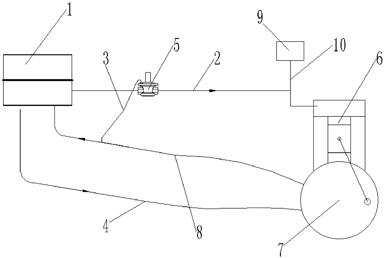
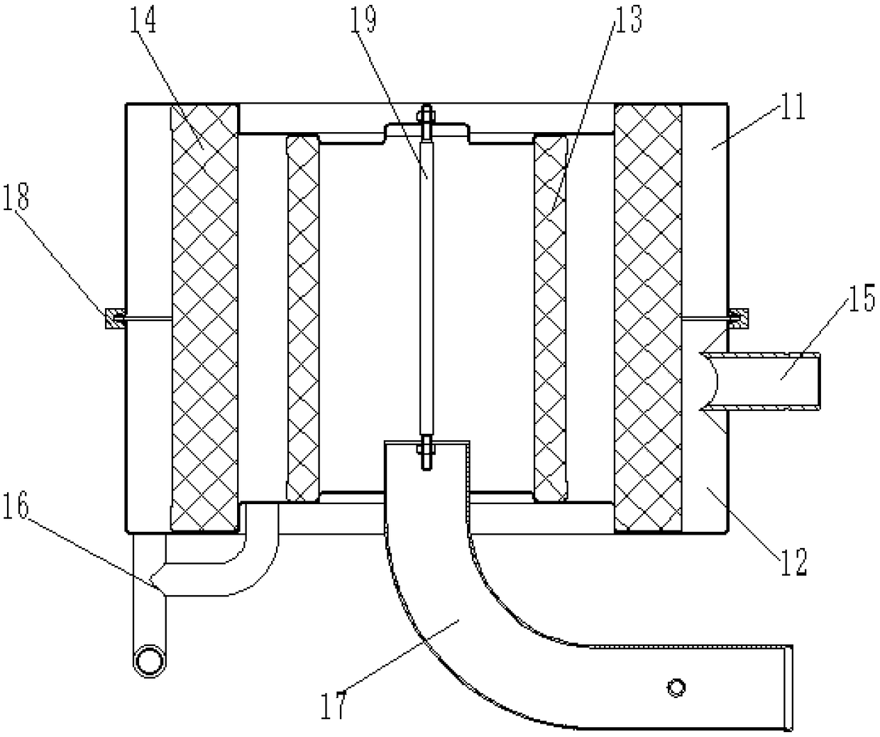
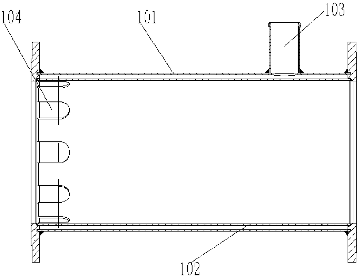
[0033] Such as figure 1 - image 3 As shown, the embodiment of the present invention provides a crankcase 7 ventilation system, including an oil-gas separator 1, an air return pipe 2, a balance pipe 3, an oil return pipe 4, a pressure regulating valve 5, an internal combustion engine 6, a crankcase 7 and a ventilation pipe 8; The crankcase 7 is communicated with the oil-gas separator 1 through the ventilation pipe 8, and the oil-gas mixture in the crankcase 7 can be passed into the oil-gas separator 1, and the oil-gas separator 1 case is communicated with the crankcase 7 through the oil return pipe 4, and the separated The oil is passed into the oil-gas separator 1, and the tank of the oil-gas separator 1 communicates with the internal combustion engine 6 through the air return pipe 2, and the separated mixed gas can be passed into the internal combustion engine 6; the pressure regulating valve 5 is connected in series with the air return pipe 2, and the crankcase 7 is balance...

Embodiment 2

[0057] An embodiment of the present invention provides a gas engine, including the crankcase 7 ventilation system as described above.

[0058] In the gas engine provided by the embodiment of the present invention, by adopting the crankcase 7 ventilation system of the above-mentioned embodiment, the combustible mixed gas filtered by the oil-gas separator 1 is passed through the return pipe 2 into the combustion chamber of the internal combustion engine 6 for secondary combustion, reducing the pollution of the environment. Simultaneously, the engine oil filtered out by the oil-air mixture in the oil-air separator 1 will flow into the crankcase 7 again through the oil return pipe 4, so as to ensure the normal amount of oil in the crankcase 7. Finally, by connecting the pressure regulating valve 5 in series on the air return pipe 2, and making the crankcase 7 communicate with the diaphragm upper chamber of the pressure regulating valve 5 through the balance pipe 3, the pressure in...


PUM


Abstract

The invention provides a crankcase ventilation system and a gas engine and relates to the technical field of oil gas treatment of crankcases of gas engines. The crankcase ventilation system comprisesan oil gas separator, a gas return pipe, a balancing pipe, an oil return pipe, a pressure adjusting valve, an internal-combustion engine, a crankcase and a ventilation pipe, wherein the crankcase communicates to the oil gas separator through the ventilation pipe and an oil and gas mixture can be introduced into the oil gas separator; an oil gas separator box communicates to the crankcase through the oil return pipe, and separated oil can be introduced into the oil gas separator; the oil gas separator box communicates to the internal-combustion engine through the gas return pipe, and separatedmixed gas can be introduced into the internal-combustion engine; the pressure regulating valve is connected to the gas return pipe in series, the crankcase communicates to an upper cavity of a membrane of the pressure regulating valve through the balancing pipe, and the flow of the mixed gas introduced into the crankcase through the gas return pipe can be adjusted. The system alleviates the technical problems that the crankcase ventilation system in the prior art is large in oil consumption, emission is deteriorated, and the pressure of the crankcase cannot be controlled effectively while filtering the gas.

Description

technical field [0001] The invention relates to the technical field of gas engine crankcase oil and gas treatment, in particular to a crankcase ventilation system and a gas engine. Background technique [0002] During operation of the internal combustion engine, combustion gases can leak between the cylinders and the corresponding piston rings and enter the crankcase of the internal combustion engine. Leakage gases usually include CO, NOX, nitrogen and hydrogen compounds, unburned fuel, oil mist and water vapour. Most of these gases are hazardous and need to be dealt with by the crankcase ventilation system. [0003] The crankcase ventilation system or device currently used in the market generally filters gas through a simple oil-gas separator. This kind of crankcase ventilation system or device has poor filtering accuracy for oil and gas, and cannot separate the oil and gas discharged from the crankcase well. mixture, and its filtered gas discharge port is directly discha...

Claims


Application Information

Patent Timeline
IPC IPC(8): F01M13/00F01M13/04
CPCF01M13/00F01M13/0011F01M13/04F01M2013/0016
Inventor 雷爱国邓海军
Owner 湖南省力宇燃气动力有限公司
Why Eureka
Try Eureka