High-abrasion-resistance hydraulic valve

A high wear resistance, hydraulic valve technology, applied in the field of hydraulic valve body, can solve the problems of aggravated loss, casualties, equipment unusable, etc., achieve not easy overflow, good insulation and corrosion resistance, and ensure normal and stable operation Effect

Inactive Publication Date: 2018-11-06
JIANGSU TIANZIGE NEW MATERIAL TECH CO LTD
View PDF0 Cites 0 Cited by
  • Summary
  • Abstract
  • Description
  • Claims
  • Application Information

AI Technical Summary

Problems solved by technology

Explanation of terms: hydraulic valve is an automatic component operated by pressure oil, which is controlled by pressure oil of pressure distribution valve, usually used in combination with electromagnetic pressure distribution valve, and can be used to remotely control the on-off of oil, gas and water pipeline systems in hydropower stations , The hydraulic valve body is made of low-alloy gray cast iron, which not only has low strength, but also has serious shrinkage and loose structure, and the structure is not dense
Due to the low strength, fractures often occur under the action of high pressure and heavy load, which may cause the equipment to be unusable and affect production, and cause casualties or property losses in severe cases; Under the action, hydraulic oil leakage often occurs, causing the cylinder to release pressure, which seriously affects the working efficiency of the equipment
[0003] The existing hydraulic valve body has a complex design structure and poor airtightness of the whole device, which leads to the contamination of the hydraulic oil, which leads to increased wear of the hydraulic valve and aggravates its loss, which is not conducive to its long-term maintenance and use

Method used


Image

  • High-abrasion-resistance hydraulic valve
  • High-abrasion-resistance hydraulic valve

Examples


Embodiment Construction

[0015] The following will clearly and completely describe the technical solutions in the embodiments of the present invention with reference to the accompanying drawings in the embodiments of the present invention. Obviously, the described embodiments are only some, not all, embodiments of the present invention. Based on the embodiments of the present invention, all other embodiments obtained by persons of ordinary skill in the art without making creative efforts belong to the protection scope of the present invention.

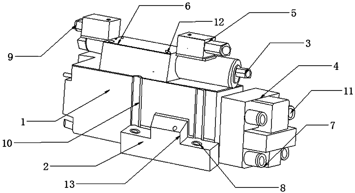
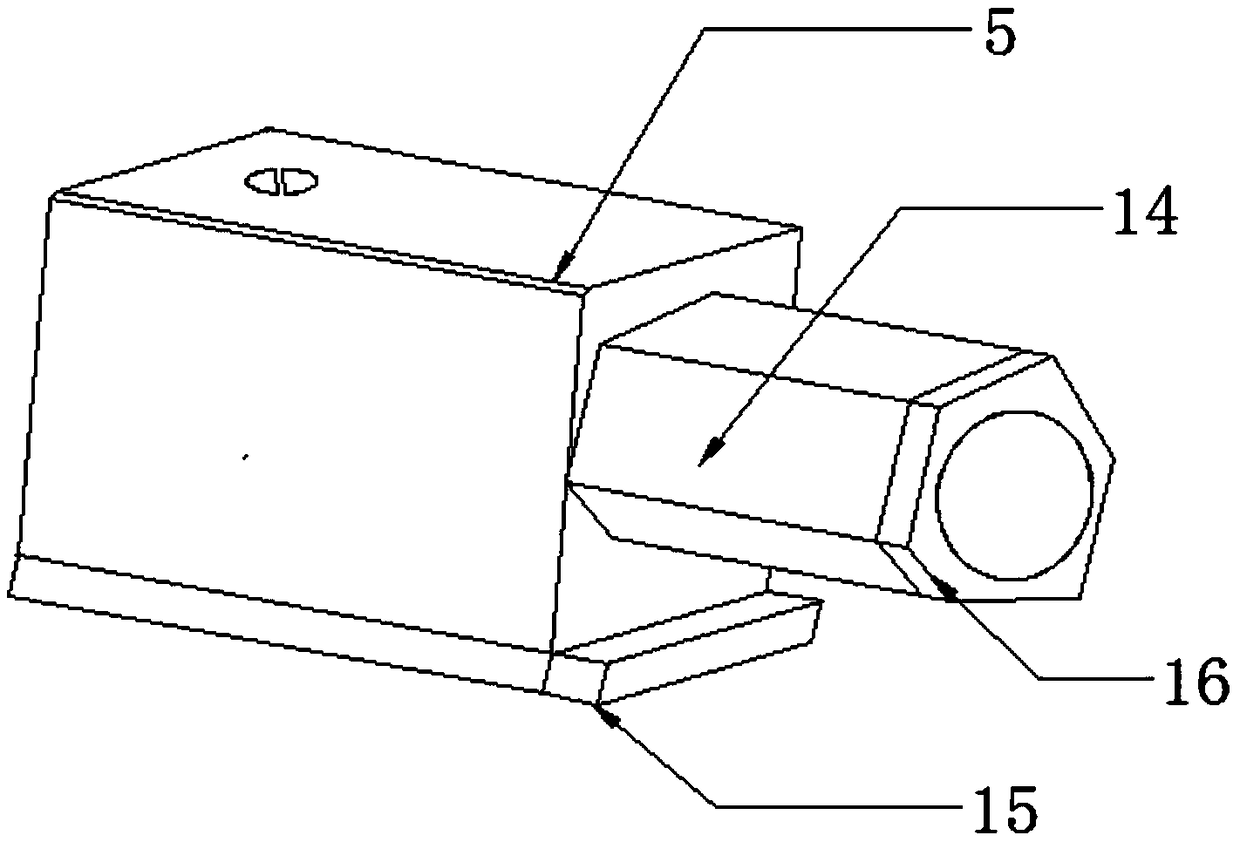
[0016] see Figure 1-2 , the present invention provides a technical solution: a hydraulic valve body with high wear resistance, including a valve body 1, a valve seat 2, and a forward oil inlet 3, the top of the valve body 1 is provided with a pressure chamber 6, so The adjacent side of the pressure chamber 6 is provided with a long hole screw 12, and the pressure chamber 6 and the valve body 1 are fixed by the long hole screw 12, and the side of the pressure ...


PUM


Abstract

The invention discloses a high-abrasion-resistance hydraulic valve which comprises a valve body, a valve seat and a forward oil inlet, wherein a pressure cavity is arranged at the top of the valve body; long-hole screws are arranged on the adjacent sides of the pressure cavity; the pressure cavity and the valve body are fixed through the long-hole screws; an upper cover is arranged on one side ofthe pressure cavity; and the upper cover and the pressure cavity are welded. Relatively good sealing measures are adopted for the entire high-abrasion-resistance hydraulic valve, and special rubber protecting shields and sealing gaskets are arranged, so that hydraulic oil can be prevented from being polluted by external dust or other impurities, and then the circumstance that a hydraulic cylinderis damaged because the frictional loss is increased during the work of the valve body can be avoided; a control piston is equipped with a ceramic protecting layer, and the ceramic protecting layer hasrelatively good insulation and corrosion-resistant effects, so that the use of the control piston can be protected; and furthermore, the valve body is equipped with a reinforcing key, so that the higher stationarity of the valve body during the work can be guaranteed, the possibility that the hydraulic oil in the hydraulic cylinder overflows can be low, and the normal and stable running of the hydraulic oil of the valve body can be ensured.

Description

technical field [0001] The invention relates to the technical field of hydraulic valve bodies, in particular to a hydraulic valve body with high wear resistance. Background technique [0002] The hydraulic valve is an automatic component operated by pressure oil. It is controlled by the pressure oil of the pressure distribution valve. It is usually used in combination with the electromagnetic pressure distribution valve. It can be used to remotely control the on-off of the oil, gas and water pipeline system of the hydropower station. Commonly used in clamping, control, lubrication and other oil circuits. There are direct-acting and pilot-operated types, and the pilot-operated type is mostly used. Explanation of terms: hydraulic valve is an automatic component operated by pressure oil, which is controlled by pressure oil of pressure distribution valve, usually used in combination with electromagnetic pressure distribution valve, and can be used to remotely control the on-off...

Claims


Application Information

Patent Timeline
IPC IPC(8): F15B13/02F16K27/00
CPCF15B13/021F16K27/00
Inventor 丁左宏
Owner JIANGSU TIANZIGE NEW MATERIAL TECH CO LTD
Why Eureka
Try Eureka